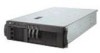
IBM 4500R Hardware Maintenance Manual
IBM 4500R - Netfinity - 8656 Manual
 |
UPC - 087944567837
View all IBM 4500R manuals
Add to My Manuals
Save this manual to your list of manuals |
IBM 4500R manual content summary:
- IBM 4500R | Hardware Maintenance Manual - Page 1
Hardware Maintenance Manual Netfinity 4500R Type 8656 IBM - IBM 4500R | Hardware Maintenance Manual - Page 2
- IBM 4500R | Hardware Maintenance Manual - Page 3
Hardware Maintenance Manual Netfinity 4500R Type 8656 IBM - IBM 4500R | Hardware Maintenance Manual - Page 4
product it supports, be sure services, and features available in your area. Requests for technical information about IBM products should be made to your IBM reseller or IBM marketing representative. © Copyright International Business Machines Corporation 2000. All rights reserved. US Government Users - IBM 4500R | Hardware Maintenance Manual - Page 5
for the Netfinity 4500R (Type 8656, Models 1RY, 2RY). Important: This manual is intended for trained servicers who are familiar with IBM PC Server products. Important safety information Be sure to read all caution and danger statements in this book before performing any of the instructions. Leia - IBM 4500R | Hardware Maintenance Manual - Page 6
de precaución y peligro ante de llevar a cabo cualquier operación. Online support Use the World Wide Web (WWW) to download Diagnostic, BIOS Flash, and Device Driver files, and documents. The web address is: http://www.ibm.com/pc/support iv Hardware Maintenance Manual: Netfinity 4500R Type 8656 - IBM 4500R | Hardware Maintenance Manual - Page 7
16 Network connection problems 16 Ethernet controller troubleshooting chart 17 Ethernet controller messages 19 Novell NetWare or IntraNetWare server ODI driver messages 19 Network driver interface specification 2.01 (OS/2) driver messages 22 NDIS 4.0 (Windows NT) driver messages 23 UNIX - IBM 4500R | Hardware Maintenance Manual - Page 8
inspection guide 143 Handling electrostatic discharge-sensitive devices 144 Grounding requirements 145 Safety notices (multi-lingual translations 145 Send us your comments 180 Problem determination tips 181 Notices 181 Trademarks 182 vi Hardware Maintenance Manual: Netfinity 4500R Type 8656 - IBM 4500R | Hardware Maintenance Manual - Page 9
components of the server: the system you cannot determine whether a problem is caused by the hardware programs, a single problem might cause several error go to "Undetermined problems" on page 133. 5. Power supply problems, see "Power page 141. 7. For intermittent problems, check the error log; - IBM 4500R | Hardware Maintenance Manual - Page 10
programs" on page 14. • Check for the following responses: a. One beep. b. Readable instructions or the Main Menu. 3. DID YOU RECEIVE BOTH OF THE CORRECT RESPONSES? NO. Find you still suspect a problem, see "Undetermined problems" on page 133. 2 Hardware Maintenance Manual: Netfinity 4500R Type 8656 - IBM 4500R | Hardware Maintenance Manual - Page 11
World Wide Web address: http://www.ibm.com/pc/us/netfinity/ Features and specifications The following table provides a summary of the features and specifications for your Netfinity 4500R server. Microprocessor: • Intel® Pentium III • 256 KB Level-2 cache • Supports up to two microprocessors Memory - IBM 4500R | Hardware Maintenance Manual - Page 12
ft.) to 2133 m (6998 ft.) - Server off: 10º to 43º C (50º to 109.4º F). Maximum altitude: 2133 m (6998 ft.) • Humidity: - Server on: 8% to 80% - Server off: 8% to 80% Heat output: • kilovolt-amperes (kVA) approximately: - Minimum: 0.08 kVA 4 Hardware Maintenance Manual: Netfinity 4500R Type 8656 - IBM 4500R | Hardware Maintenance Manual - Page 13
Server features The Netfinity 4500R server is designed to be cost-effective, powerful, and flexible. Your server offers: • Impressive performance using an innovative approach to SMP Your server supports up to two Intel Pentium III microprocessors. Your server comes with one microprocessor installed - IBM 4500R | Hardware Maintenance Manual - Page 14
user intervention. • Optional digital linear tape drive The addition of an optional digital linear tape drive (DLT) allows quick backup of large amounts of data. • IBM ServerGuide CDs The ServerGuide CDs included with your Netfinity servers provide programs to help you set up your server and install - IBM 4500R | Hardware Maintenance Manual - Page 15
are on the front panel of the server. 1 AC power light 2 Hard Disk system power is present in the server. When this light flashes, the server is in standby mode (the system server. The light might be burned out. To remove all electrical current from the server, you must unplug the server - IBM 4500R | Hardware Maintenance Manual - Page 16
system, if this feature is supported by your operating system, and places the server in standby mode. Note: After turning off the server, wait at least 5 seconds Press this button to reset the server and run the power-on self-test (POST). 8 Hardware Maintenance Manual: Netfinity 4500R Type 8656 - IBM 4500R | Hardware Maintenance Manual - Page 17
of lights, see "Power supply LED errors" on page 121. Operator Information Panel: The lights on this panel give status information for your server. See "Operator information panel" for more information. DC Power Light: This light provides status information about the power supply. During normal - IBM 4500R | Hardware Maintenance Manual - Page 18
the information log contains information about certain conditions in your server that might affect performance. For example, the light will be on if your server does not have redundant power. A light on the be on to further isolate the error. 10 Hardware Maintenance Manual: Netfinity 4500R Type 8656 - IBM 4500R | Hardware Maintenance Manual - Page 19
Diagnostics This section provides basic troubleshooting information to help you resolve some common problems that might occur with your server. Diagnostic tools overview The following tools are available to help you identify and resolve hardware-related problems: • POST beep codes, error messages, - IBM 4500R | Hardware Maintenance Manual - Page 20
problems using these LEDs. PS1 PS2 PS3 NON OVER NMI TEMP FAN MEM CPU PCI A PCI B VRM server components and some of the options installed in the server. This series of tests is called the power-on self-test or POST. If POST finishes without detecting any problems Manual: Netfinity 4500R Type 8656 - IBM 4500R | Hardware Maintenance Manual - Page 21
Netfinity server does not have a hard disk drive, ignore any message that indicates that the drive is not installed server. Diagnostic error messages indicate that a problem exists; they are not intended to be used to identify a failing part. Troubleshooting and servicing of complex problems - IBM 4500R | Hardware Maintenance Manual - Page 22
: Test Specific String This is additional information that you can use to anayze the problem. Passed problem is reported during the diagnostic test, such as when a device that is to be tested is not installed instructions on the screen. 14 Hardware Maintenance Manual: Netfinity 4500R Type 8656 - IBM 4500R | Hardware Maintenance Manual - Page 23
(DMA) use, device drivers, and so on) by selecting Hardware Info from the top of the screen. When the tests have completed, you can view the Test Log by selecting Utility from the top of the screen. If the hardware checks out OK but the problem persists during normal server operations, a software - IBM 4500R | Hardware Maintenance Manual - Page 24
installed correctly. The network cable must be securely attached at all connections. If the cable is attached but the problem persists, try a different cable. If you set the Ethernet controller to operate at 100 Mbps, you must use Category 5 cabling. 16 Hardware Maintenance Manual: Netfinity 4500R - IBM 4500R | Hardware Maintenance Manual - Page 25
• Determine if the hub supports auto-negotiation. If not, try configuring the integrated Ethernet controller manually to match the speed and drivers, supplied with your server. • Check for operating system-specific causes for the problem. • Make sure that the device drivers on the client and server - IBM 4500R | Hardware Maintenance Manual - Page 26
device drivers. Data is incorrect or sporadic. Check the following: • Make sure that you are using Category 5 cabling when operating the server at 100 Mbps. • Make sure that the cables do not run close to noise-inducing sources like fluorescent lights. 18 Hardware Maintenance Manual: Netfinity 4500R - IBM 4500R | Hardware Maintenance Manual - Page 27
Adapter for level 4.0 (Windows NT) • SCO™ UNIX LLI Novell NetWare or IntraNetWare server ODI driver messages This section provides explanations of the error messages for the Novell NetWare or IntraNetWare server ODI driver, and suggested actions to resolve each problem. Table 2. Novell NetWare or - IBM 4500R | Hardware Maintenance Manual - Page 28
of the driver with a different I/O address. This new adapter could not be found. Action: Verify that you installed an IBM Netfinity 10/100 driver is correct for the version of NetWare or IntraNetWare that you are using. Restart the server. 20 Hardware Maintenance Manual: Netfinity 4500R Type 8656 - IBM 4500R | Hardware Maintenance Manual - Page 29
14 to run the diagnostic programs. PCNTNW-NW-087 The media parameter block is too small. Explanation: The driver media parameter block is too small. Action: Restart the server. If the problem persists, go to "Starting the diagnostic programs" on page 14 to run the diagnostic programs. PCNTNW-NW-091 - IBM 4500R | Hardware Maintenance Manual - Page 30
driver cannot locate the Ethernet controller on the PCI bus. Action: Verify that the Ethernet controller is enabled. If the Ethernet controller is enabled, go to "Starting the diagnostic programs" on page 14 to run the diagnostic programs. 22 Hardware Maintenance Manual: Netfinity 4500R Type 8656 - IBM 4500R | Hardware Maintenance Manual - Page 31
Mode is disabled. PermaNet Server: Explanation: The failover option requires an adapter that is compatible with the device driver of the Ethernet controller on the system board. No such adapter was found. Action: Make sure the correct adapter is installed. Problem Occurs on the Primary Adapter - IBM 4500R | Hardware Maintenance Manual - Page 32
driver cannot find any more Ethernet controllers. Action: Verify that additional IBM Netfinity 10/100 Fault Tolerant Adapters are present or replace the Ethernet adapter that fails to respond. If the problem persists, run the diagnostic programs. 24 Hardware Maintenance Manual: Netfinity 4500R - IBM 4500R | Hardware Maintenance Manual - Page 33
driver has been reset due to a device fault. Action: Verify that additional IBM Netfinity 10/100 Fault Tolerant Adapters are present or replace the Ethernet adapter that fails to respond. If the problem found, conflicts with other devices in the server. Action: • Modify your hardware settings. - IBM 4500R | Hardware Maintenance Manual - Page 34
" on page 45. Follow any special handling and installation instructions supplied with the replacement battery. Note: After you replace the battery, you must reconfigure your server and reset the system date and time. To replace the battery: 26 Hardware Maintenance Manual: Netfinity 4500R Type 8656 - IBM 4500R | Hardware Maintenance Manual - Page 35
installation instructions supplied with the replacement battery. 2. Turn off the server and peripheral devices and disconnect all external cables and power cords; then, remove the server Netfinity server, you should make sure: • Each of the drive bays has either a drive or a filler panel installed - IBM 4500R | Hardware Maintenance Manual - Page 36
48 hours In addition, ensure that the environmental specifications for the system are met. See "Features and specifications" on page 3. For more information on specific temperature error messages, see "Temperature error messages" on page 128. 28 Hardware Maintenance Manual: Netfinity 4500R Type 8656 - IBM 4500R | Hardware Maintenance Manual - Page 37
CDs include software setup and installation tools specifically designed for IBM Netfinity servers. You can use these CDs during the initial installation of your server to configure the server hardware and simplify your network operating system installation. The ServerGuide CDs also contain - IBM 4500R | Hardware Maintenance Manual - Page 38
the following: IBM - © IBM Corporation 2000 of memory installed. Changes server serial number, and the revision level or issue date of the BIOS stored in the flash electronically erasable programmable ROM (EEPROM). - System Card Data 30 Hardware Maintenance Manual: Netfinity 4500R Type 8656 - IBM 4500R | Hardware Maintenance Manual - Page 39
change the system time sent to the Configuration/Setup Utility (service processor) when the server is started. This choice appears only on the full Configuration on passwords, and allow a power-on password to be changed by the user. See "Using passwords" on page 34 for more information. - System - IBM 4500R | Hardware Maintenance Manual - Page 40
installed in the server. You can enable a virus-detection test that checks for changes in the master boot instructions IBM authorized service server configuration information. This usually results in automatic configuration of a PCI device. 32 Hardware Maintenance Manual: Netfinity 4500R Type 8656 - IBM 4500R | Hardware Maintenance Manual - Page 41
installed, the server will have no video capability. However, turning the server server can automatically disable the failing memory bank and continue operating with reduced memory capacity. If this occurs, you must manually enable the memory bank after the problem Utility (system service processor). - IBM 4500R | Hardware Maintenance Manual - Page 42
you forget the power-on password, you can regain access to the server through one of the following methods: • If an administrator password is password override switch". • Remove the battery and then install the battery. Setting the password override switch: The Manual: Netfinity 4500R Type 8656 - IBM 4500R | Hardware Maintenance Manual - Page 43
switch block 1 on the system board) to ON. 4. Install the server cover (see "Installing the server cover and bezel" on page 60) and connect all external passwords, and allow a power-on password to be changed by the user. Attention: If an administrator password is set and then forgotten, it cannot - IBM 4500R | Hardware Maintenance Manual - Page 44
instructions needed to start the SCSISelect Utility and descriptions of the menu choices available. Note: If your server has a RAID adapter installed instructions on the screen to change the settings of the selected items; then, press Enter. 36 Hardware Maintenance Manual: Netfinity 4500R Type 8656 - IBM 4500R | Hardware Maintenance Manual - Page 45
values, press F6; then, follow the instructions that appear on the screen. You assigned value of Automatic. - Boot Device Options Select this choice to enabling support for large hard disk drives and support Failure screen might appear. Restart the server and watch the SCSISelect messages as each - IBM 4500R | Hardware Maintenance Manual - Page 46
instructions on the screen. Note: Hard disks normally contain more tracks than their stated capacity (to allow for defective tracks). A message appears on the screen if the defect limit is reached. If this happens, have the system serviced. 38 Hardware Maintenance Manual: Netfinity 4500R Type 8656 - IBM 4500R | Hardware Maintenance Manual - Page 47
to help you add options to your server. Some option-removal instructions are provided, in case you need to remove one option to install another. Exploded view of the Netfinity 4500R The orange color on components and labels in your server identifies hot-swap or hotplug components. This means - IBM 4500R | Hardware Maintenance Manual - Page 48
The following illustration shows a layout of the system board and identifies systemboard connectors for user-installable options. 1 PCI slot 5 32-bit (J44) 2 Battery 3 PCI slot 4 (U3) 13 Voltage regulator module 2 (VRM2) (U26) 40 Hardware Maintenance Manual: Netfinity 4500R Type 8656 - IBM 4500R | Hardware Maintenance Manual - Page 49
panel (J38) 13 IDE (J31) 14 Diskette (J26) System board external port connectors The following illustration shows the external port connectors in the system board. Installing options 41 - IBM 4500R | Hardware Maintenance Manual - Page 50
port (J6) 6 Serial ports (J3) System board switches and jumpers The following illustration identifies the switches and jumpers on the system board. 42 Hardware Maintenance Manual: Netfinity 4500R Type 8656 - IBM 4500R | Hardware Maintenance Manual - Page 51
in the illustration are reserved. For normal operation of the system, no jumpers should be installed on any of the jumper blocks. See "Recovering BIOS" on page 16 for information about the boot block jumper. System board switch block The switch block contains microswitches 1-8. As shown in this - IBM 4500R | Hardware Maintenance Manual - Page 52
require the user to enter problems with the server. 1 Secondary microprocessor failure (CR7) 2 Primary microprocessor failure (CR1) 3 Voltage regulator module (VRM2) failure (CR16) 4 Integrated voltage regulator (VRM1) failure (CR4) 44 Hardware Maintenance Manual: Netfinity 4500R Type 8656 - IBM 4500R | Hardware Maintenance Manual - Page 53
PCI 1 PCI 2 VRM DASD1 DASD2 Description Power supply 1 server indentifies hot-swap or hot-plug components. This means that you can install or remove the component while the system is running, provided that your system is configured to support this function. For complete details about installing - IBM 4500R | Hardware Maintenance Manual - Page 54
until you are instructed to do so. When you handle options and other server components, take these precautions to avoid damage from static electricity: • Limit your movement. Movement can cause static electricity to build up around you. 46 Hardware Maintenance Manual: Netfinity 4500R Type 8656 - IBM 4500R | Hardware Maintenance Manual - Page 55
at least two seconds. (This reduces static electricity from the package and from your body.) • When possible, remove the option and install it directly into the server without setting the option down. When this is not possible, place the static-protective package that the option comes in on a smooth - IBM 4500R | Hardware Maintenance Manual - Page 56
with the adapter. • You can install full-length adapters in all expansion slots. • You can install a 32-bit RAID adapter in any of the PCI slots, but you might want to install it in a 32-bit slot and use the 64-bit slots for 64-bit adapters. 48 Hardware Maintenance Manual: Netfinity 4500R Type 8656 - IBM 4500R | Hardware Maintenance Manual - Page 57
3 through 5. You can use the Configuration/Setup Utility program to change the boot precedence for your server. Select Start Options from the Configuration/Setup Utility program. Adapter installation instructions 1 Adapter 2 Expansion-slot cover The following illustration shows the rerouting of - IBM 4500R | Hardware Maintenance Manual - Page 58
, go to "Installing the server cover and bezel" on page 60. Installing internal drives If you add different types of drives, your system can read multiple types of media and store more data. Several types of drives are available, such as: 50 Hardware Maintenance Manual: Netfinity 4500R Type 8656 - IBM 4500R | Hardware Maintenance Manual - Page 59
a 3-Pack Hard-Disk Drive option, which converts these bays to three hot-swap drive bays. • The Netfinity 4500R server supports only one diskette drive. • If you are installing a device with a 50-pin connector in either bay A or B, you need a 68-pin to 50-pin converter (option number 32G3925 - IBM 4500R | Hardware Maintenance Manual - Page 60
installing a hot-swap hard disk drive. If you want to remove a drive, reverse the following steps. Notes: 1. To minimize the possibility of damage to the hard disk drives, install the server in the rack before installing the hard disk drives. 52 Hardware Maintenance Manual: Netfinity 4500R Type 8656 - IBM 4500R | Hardware Maintenance Manual - Page 61
server. 3. Install guide rails in the bay. c. Gently push the drive/tray assembly into the bay until the drive connects to the backplane. d. Push the tray handle down until it locks. 4. Check the hard disk drive status indicators to verify that the hard disk drive is operating properly. Installing - IBM 4500R | Hardware Maintenance Manual - Page 62
to the documentation that comes with the drive. 7. Install rails on the drive. • If you are installing a standard-size drive: a. Pull the blue slide rails off the back of the filler panel. b. Clip the rails onto the sides of the drive. 54 Hardware Maintenance Manual: Netfinity 4500R Type 8656 - IBM 4500R | Hardware Maintenance Manual - Page 63
and the IBM Bulletin Board System (BBS). The latest level of BIOS for your server is available through the World Wide Web 2. Obtain an SMP-capable operating system (optional). For a list of supported operating systems, see http://www.ibm.com/pc/us/compat/ on the World Wide Web. Installing options 55 - IBM 4500R | Hardware Maintenance Manual - Page 64
installed it becomes the BOOT processor and the original processor (microprocessor 1) becomes the application processor. Attention: To avoid damage and ensure proper server operation when you install VRM 4 Microprocessor 1 5 VRM connector 56 Hardware Maintenance Manual: Netfinity 4500R Type 8656 - IBM 4500R | Hardware Maintenance Manual - Page 65
the microprocessor kit. Attention: When installing or replacing a VRM, use only a VRM specified for use with the Netfinity 4500R server. Use of other VRMs might cause your server to overheat. a. Center the VRM over the VRM connector. Make sure that the VRM is oriented and aligned correctly. b. Press - IBM 4500R | Hardware Maintenance Manual - Page 66
and pulling it away from the server. Save the filler panel in case you remove the power supply at a later time. Note: During normal operation, each power-supply bay must have either a power supply or filler panel installed for proper cooling. 58 Hardware Maintenance Manual: Netfinity 4500R Type 8656 - IBM 4500R | Hardware Maintenance Manual - Page 67
the replacement fan assembly into the server until it clicks into place. 4. Verify that the FAN LED on the diagnostics panel on the system board is not lit. If the FAN LED is lit, reseat the fan. 5. Replace the cover. See "Installing the server cover and bezel" on page 60. Installing options 59 - IBM 4500R | Hardware Maintenance Manual - Page 68
with the slots on the server chassis. 2. Close the cover-release latch. To install the bezel: 1. Align the trim bezel with the front of the server. 2. Press inward on Adhering to these standards ensures that your server operates properly. 60 Hardware Maintenance Manual: Netfinity 4500R Type 8656 - IBM 4500R | Hardware Maintenance Manual - Page 69
procedure To attach an external device: 1. Turn off the server and all attached devices. 2. Follow the instructions that come with the option to prepare it for installation and to connect it to the server. Input/Output ports This section provides information about the input/output (I/O) ports - IBM 4500R | Hardware Maintenance Manual - Page 70
bidirectional mode, the server supports the ECP and EPP modes. To view or change the parallel-port assignment: 1. Restart the server and watch the I/O Data 5 8 I/O Data 6 EPP Signal -WRITE Data 0 Data 1 Data 2 Data 3 Data 4 Data 5 Data 6 62 Hardware Maintenance Manual: Netfinity 4500R Type 8656 - IBM 4500R | Hardware Maintenance Manual - Page 71
graphics array (SVGA) video controller. This controller is not removable, but you can disable it by installing a PCI video adapter. Note: If you install a PCI video adapter, the server BIOS will automatically disable the integrated video adapter. The following table shows the pin-number assignments - IBM 4500R | Hardware Maintenance Manual - Page 72
device) port The system board has one auxiliary-device port that supports a mouse or other pointing device. The following table shows the pin-number assignments for the auxiliary-device connector on the rear of your server. 6 4 2 5 3 1 64 Hardware Maintenance Manual: Netfinity 4500R Type 8656 - IBM 4500R | Hardware Maintenance Manual - Page 73
external. Each of these channels supports up to 15 SCSI devices. In server, a SCSI cable connects the internal SCSI channel connector to the hot-swap drive backplane. Note: If you install use with external devices, contact your IBM reseller or IBM marketing representative. For information about the - IBM 4500R | Hardware Maintenance Manual - Page 74
ID for the device. Refer to the information that is provided with the device for instructions to set its SCSI ID. SCSI connector pin-number assignments The following table shows the 58 -Acknowledge 59 -Reset 60 -Message 61 -Select 66 Hardware Maintenance Manual: Netfinity 4500R Type 8656 Signal - IBM 4500R | Hardware Maintenance Manual - Page 75
server has two standard serial ports: Serial port A and Serial port B. The operating system can use and share both serial ports; however, the integrated Netfinity Advanced System Management Processor can use and share only Serial port A. Some application programs require specific the server server. - IBM 4500R | Hardware Maintenance Manual - Page 76
be disabled during the power-on self-test (POST). 2. If you install a USB keyboard that has a mouse port, the USB keyboard emulates a server. Table 15. USB-port connector pin-number assignments. Pin 1 2 3 4 VCC -Data +Data Ground Signal 68 Hardware Maintenance Manual: Netfinity 4500R Type 8656 - IBM 4500R | Hardware Maintenance Manual - Page 77
(FDX). The controller supports half-duplex (HDX) drivers are provided on the ServerGuide CDs. Failover for redundant Ethernet The IBM Netfinity 10/100 Fault Tolerant Adapter is an optional redundant network interface card (NIC adapter) that you can install in your server. If you install user manually - IBM 4500R | Hardware Maintenance Manual - Page 78
. The Ethernet controller in your computer is DMI compliant. Download and install the following software in the order listed: 1. IBM Failover DMI Agent 2. IBM PCI Hot Plug Solution 3. IBM Netfinity 10/100 Fault Tolerant Adapter device drivers 70 Hardware Maintenance Manual: Netfinity 4500R Type 8656 - IBM 4500R | Hardware Maintenance Manual - Page 79
The setup wizard opens. 6. Follow the instructions that are given by the setup wizard until the program is installed. 7. Restart the server. To install the IBM PCI Hot Plug Solution package: 1. Download the IBM PCI Hot Plug Services EXE file from the Netfinity Support web page and extract the files - IBM 4500R | Hardware Maintenance Manual - Page 80
swapped. Users with the IBM Netfinity Hot Plug PCI for Windows NT Server 4.0 package installed should check the Enable for DMI / Hot Swap Support checkbox. If the Enable for DMI / Hot Swap Support checkbox command: LOAD d:\path\PCNTNW SCAN 72 Hardware Maintenance Manual: Netfinity 4500R Type 8656 - IBM 4500R | Hardware Maintenance Manual - Page 81
the drive and path where the driver is located. This command causes the device driver to locate the primary adapter and switch D-shell system-management connector on the rear of your server to communicate with the integrated Netfinity Advanced System Management Processor. The RS-485 function uses - IBM 4500R | Hardware Maintenance Manual - Page 82
11 Serial B 12 Power supply 2 power cord connector Refer to the following illustration for the routing of cables through the cablemanagement arm. 74 Hardware Maintenance Manual: Netfinity 4500R Type 8656 - IBM 4500R | Hardware Maintenance Manual - Page 83
in your network. Furthermore, additional Netfinity Manager and Client Services for Netfinity Manager licenses are available for purchase from your IBM representative. Note: This section provides installation instructions for all operating systems supported by Netfinity Manager. However, not all - IBM 4500R | Hardware Maintenance Manual - Page 84
95 and Windows 98 system requirements The minimum system requirements for Netfinity Manager for Windows 95 are: • Microsoft Windows 95 or later • Approximately 17 MB-20 MB of hard disk space (space required depends on system configuration) 76 Hardware Maintenance Manual: Netfinity 4500R Type 8656 - IBM 4500R | Hardware Maintenance Manual - Page 85
with Service Pack 1 and WCPIC32.DLL dated 01/22/97 or later. This DLL is available from Microsoft) Note: Systems using Netfinity Manager with Microsoft SNA Server cannot communicate with systems that run the Microsoft SNA Server client. Netfinity Manager supports only server-to-server communications - IBM 4500R | Hardware Maintenance Manual - Page 86
Services for Netfinity Manager from the Available Applications list and then refer to the Client Services for Netfinity Manager User's Guide for additional installation instructions. e. Click Install Product to start the installation process. 78 Hardware Maintenance Manual: Netfinity 4500R Type 8656 - IBM 4500R | Hardware Maintenance Manual - Page 87
Netfinity Manager program offers several installation options. Each option enables additional specialized feature of this product. The available installation options are: • Advanced System Management Support Click Advanced System Management Support to install the Advanced System Management service - IBM 4500R | Hardware Maintenance Manual - Page 88
for network access, enter information regarding the communication protocols that are supported by the system. The Network Driver Configuration window will appear. Follow these steps to continue configuring the system: a. Enter a System Name. 80 Hardware Maintenance Manual: Netfinity 4500R Type 8656 - IBM 4500R | Hardware Maintenance Manual - Page 89
prevent remote Netfinity Manager users from using the Serial Connection Control service to access the system. c. Enable the Network Driver. When you have entered all required information, click the Driver Enabled check box to activate the driver on startup. If the system supports multiple network - IBM 4500R | Hardware Maintenance Manual - Page 90
for Windows 95, the installation program will display a list of changes that must be made to the CONFIG.SYS file. Click either Yes or No. Note: These changes must be made to the system configuration for Netfinity Manager to run correctly. 82 Hardware Maintenance Manual: Netfinity 4500R Type 8656 - IBM 4500R | Hardware Maintenance Manual - Page 91
or Windows NT. If the system supports ODBC, the user can access and export DB2 data through ODBC as well. Once support for one or more of these databases has been installed along with Netfinity Manager, data can be exported from these Netfinity Manager services: • Alert Manager • Software Inventory - IBM 4500R | Hardware Maintenance Manual - Page 92
Press Enter. 4. Next, you must configure the tables for ODBC database support. For information on configuring the database for ODBC, refer to "ODBC database the database installation step. c. Press Enter. 2. Bind the package and the database 84 Hardware Maintenance Manual: Netfinity 4500R Type 8656 - IBM 4500R | Hardware Maintenance Manual - Page 93
is the name of the table as specified during database installation. A listing of the Netfinity database table names can be found in the Netfinity User's Guide (Appendix H: Netfinity Relational Database Tables). Note: The Netfinity Database Administration Tool can also be used to GRANT or REVOKE - IBM 4500R | Hardware Maintenance Manual - Page 94
, catalog the node the database resides on and then catalog the database to that node. Once this step has been completed, the name of the Netfinity Manager database will appear in the System Information Tools Database Selection window. 86 Hardware Maintenance Manual: Netfinity 4500R Type 8656 - IBM 4500R | Hardware Maintenance Manual - Page 95
database support To enable the Netfinity Manager to export system data to a Lotus Notes database, the following must be done: 1. Install the Netfinity Manager database template on the Lotus Notes server. 2. Enable Netfinity Manager to export to the Lotus Notes server. Instructions on installing the - IBM 4500R | Hardware Maintenance Manual - Page 96
database is installed, enable Netfinity Manager systems to export to the Lotus Notes server. • If the Netfinity Manager system is running Netfinity Manager for information from Netfinity Manager to an easy-to-browse Lotus Notes database. 88 Hardware Maintenance Manual: Netfinity 4500R Type 8656 - IBM 4500R | Hardware Maintenance Manual - Page 97
- Microsoft SQL Server • OS/2 - Microsoft SQL Server (using the Visigenic driver provided with Microsoft SQL Server) or - IBM DB2 For detailed information about supported ODBC platforms, see Table 17 on page 91. Note: The ODBC database name must not be longer than 8 characters. Netfinity Manager 89 - IBM 4500R | Hardware Maintenance Manual - Page 98
and then click OK to open the Database Server window. The following table actions are also available: • Delete To remove the Netfinity Manager table groups from the database, click Delete and then click OK to open the Database Server window. 90 Hardware Maintenance Manual: Netfinity 4500R Type 8656 - IBM 4500R | Hardware Maintenance Manual - Page 99
for use with this release of Netfinity Manager. Table 17. Supported Netfinity Databases.. Reference by operating system and database client version. Product Win 95 IBM DB2 Version 2.1.2 Yes IBM DB2 Universal Yes Database 5.0 ODBC - IBM DB2 Version 2.1.2 Yes, DB2 Driver Win NT 3.51 Yes Yes - IBM 4500R | Hardware Maintenance Manual - Page 100
Database Tables object, which contains a handy online reference for all of the data tables in the Netfinity Manager database. For more information on Netfinity Manager database support see "Netfinity Manager database support" on page 83. 92 Hardware Maintenance Manual: Netfinity 4500R Type 8656 - IBM 4500R | Hardware Maintenance Manual - Page 101
follow. Complete instructions on how to use each of these services can be found in the service-specific chapters of the Netfinity Manager User's Guide. Advanced System Management The Advanced System Management service provides extensive functionality available for your IBM PC Server Advanced System - IBM 4500R | Hardware Maintenance Manual - Page 102
problems are corrected. This service is available servers Netfinity Manager system. DMI Browser DMI Browser enables you to examine information about the DMI-compliant hardware and software products installed in or attached to the system. 94 Hardware Maintenance Manual: Netfinity 4500R Type 8656 - IBM 4500R | Hardware Maintenance Manual - Page 103
service can warn you immediately when a remote Netfinity Manager system has start-up problems, enabling you to react quickly to problems and other RAID system tasks. This service is available for stand-alone use and network use by any system that has a supported RAID adapter. Remote Session Use - IBM 4500R | Hardware Maintenance Manual - Page 104
other similar systems you choose. Software Inventory Software Inventory enables the user to create and manage software product dictionaries that can be used to easily maintain an inventory of all application programs installed on the system. 96 Hardware Maintenance Manual: Netfinity 4500R Type 8656 - IBM 4500R | Hardware Maintenance Manual - Page 105
that support ROM-based system problems. System service is used with IBM computers. This service specific data that might not be available to the System Information Tool, including model and serial numbers and date of purchase. Finally, there are many user systems, all from Netfinity Manager. You can - IBM 4500R | Hardware Maintenance Manual - Page 106
installation and setup information Netfinity Manager for SCO for Client Services for Netfinity Manager for SCO UnixWare Read Me UnixWare. Netfinity Manager Quick Installation and setup information for Netfinity Manager. Beginnings 98 Hardware Maintenance Manual: Netfinity 4500R Type 8656 - IBM 4500R | Hardware Maintenance Manual - Page 107
Connection Manager services. These services are included with this version of Netfinity Manager. Client Services for Installation, setup, and usage information for Client Netfinity Manager for SCO Services for Netfinity Manager for SCO UnixWare. UnixWare User's Guide Installation options This - IBM 4500R | Hardware Maintenance Manual - Page 108
. To create a customized installation, the INSTALL.INI file must be edited. For example, when creating a customized Netfinity Manager for Windows 95 or NT installation, edit the INSTALL.INI file that is found on Netfinity Manager directory. 100 Hardware Maintenance Manual: Netfinity 4500R Type 8656 - IBM 4500R | Hardware Maintenance Manual - Page 109
the third section that will be installed when this choice is selected for installation. For example: ;IBM SysMgt Install Script, Version 2 (Do not remove this comment line) Netfinity Manager Installation [Manager 16900] Advanced System Management Support [ServProc 450] Capacity Manager Enhancement - IBM 4500R | Hardware Maintenance Manual - Page 110
easiest way to customize an installation is to simply put a semicolon in front of any service that you want to remove from the installation. To add a line item in a specific section, add all the 1 SAVEG.EXE CL 0 1 SAVEG.HLP CL 0 1 CUSTOM.INI 102 Hardware Maintenance Manual: Netfinity 4500R Type 8656 - IBM 4500R | Hardware Maintenance Manual - Page 111
only) Field Replacement Units (FRUs) should be replaced by qualified service personnel only. Note: Before performing any removals, read "Safety information" on page 141 and "Before you back of the cover, release the four tabs 1 and gently pry away the LED cover 2 . © Copyright IBM Corp. 2000 103 - IBM 4500R | Hardware Maintenance Manual - Page 112
cover. See "Removing the cover and bezel" on page 47. 2. Disconnect the cable. 3. Remove the screw 1 . 4. Carefully pull out drive 2 to remove. 104 Hardware Maintenance Manual: Netfinity 4500R Type 8656 - IBM 4500R | Hardware Maintenance Manual - Page 113
board cable from the system board . 3. Remove the two screws 2 . 4. Carefully slide out the board 1 . Removing the SCSI backplane assembly 1 Screw 2 SCSI Backplane FRU information (service only) 105 - IBM 4500R | Hardware Maintenance Manual - Page 114
backplane. 3. Remove the screw from the top of the backplane bracket 1 . 4. Lift the backplane from the chassis. 5. Remove the cables from the backplane 2 . 6. Remove the four screws 3 . 7. Gently lift up to remove the backplane board 2 . 106 Hardware Maintenance Manual: Netfinity 4500R Type 8656 - IBM 4500R | Hardware Maintenance Manual - Page 115
from the backplane 1 . 3. Disconnect cables from the backplane. 4. Remove the two screws 3 . 5. Remove the plastic retainer 4 . 6. Remove insulator 2 and replace on new backplane. FRU information (service only) 107 - IBM 4500R | Hardware Maintenance Manual - Page 116
swap power supplies. 5. Pull down on the cable receptacle 5 to release it from the chassis. Note: To install the receptacle, push up into the chassis opening of slot 4 . Be sure to properly replace receptacles, 1 to 1 and 2 to 2 as labeled. 108 Hardware Maintenance Manual: Netfinity 4500R Type 8656 - IBM 4500R | Hardware Maintenance Manual - Page 117
Removing the system board Netfinity 4500R 1 System board cage 2 Knobs To remove the system board: 1. Remove the cover. See "Removing the cover and bezel" cables. 5. Pull up on the two knobs 2 . 6. Pull up on the system board cage 1 to remove from the chassis. FRU information (service only) 109 - IBM 4500R | Hardware Maintenance Manual - Page 118
110 Hardware Maintenance Manual: Netfinity 4500R Type 8656 - IBM 4500R | Hardware Maintenance Manual - Page 119
supports Netfinity 4500R servers. The Symptom-to-FRU lists symptoms, errors, and the possible causes. The most likely cause is listed first. Use this Symptom-to-FRU index to help you decide which FRUs to have available when servicing Optional Processor (if installed) 2. Processor IBM Corp. 2000 111 - IBM 4500R | Hardware Maintenance Manual - Page 120
clock failed) 1. Battery 2. System Board 3-2-1 failed) (Serial port 1. System Board 3-2-2 failed) (Parallel port 1. System Board 3-2-3 (Math coprocessor failed) 1. Optional Processor (if installed) 2. Processor 3. System Board 112 Hardware Maintenance Manual: Netfinity 4500R Type 8656 - IBM 4500R | Hardware Maintenance Manual - Page 121
the server power cord from outlet, wait 30 error occurred) seconds and retry. 2. System Board 3. DIMMs 4. DASD Backplane 5. Power Supply 6. Power Supply Backplane 7. 12C Cable 3-3-3 (No operational memory in system) 1. Install or reseat the memory modules, then do a 3 boot reset - IBM 4500R | Hardware Maintenance Manual - Page 122
Netfinity log for failure; clear PFA alert; remove AC power for at least 20 seconds, reconnect, then power up system. 3. Run Information Panel diagnostics. CPU LED on 1. Processor 1 or 2. (The LED next to the failing CPU should be on.) 114 Hardware Maintenance Manual: Netfinity 4500R Type 8656 - IBM 4500R | Hardware Maintenance Manual - Page 123
(The LED next to the failing the system board that is turned on. VRM should be on.) 2. Processor indicated by the Processor LED. DASD LED on (The LED located next to the drive bay that the failing drive is installed in will be turned on.) 1. Failing drive. 2. Be sure the fans are - IBM 4500R | Hardware Maintenance Manual - Page 124
look at test 1. Ambient temperature must be within normal operating cases) specifications. See "Features and specifications" on page 3. 2. Ensure fans are operating correctly. 3. Examine Serial Port test) 1. System Board FRU/Action 116 Hardware Maintenance Manual: Netfinity 4500R Type 8656 - IBM 4500R | Hardware Maintenance Manual - Page 125
System Board 035-XXX-099 1. No adapters were found. 2. If adapter is installed re-check connection. 035-XXX-S99 (Failed 1. RAID test on PCI slot extended configuration status and refer to the ServeRAID Hardware Maintenance Manual for more information. 2. Cable 3. SCSI Backplane 4. Adapter - IBM 4500R | Hardware Maintenance Manual - Page 126
Board 202-XXX-001 System Cache test) (Failed 1. VRM 1 2. Microprocessor 1 202-XXX-002 (Failed System Cache test) 1. VRM 2 2. Microprocessor 2 206-XXX-000 (Failed Diskette Drive test) 1. Cable 2. Diskette Drive 3. System Board 118 Hardware Maintenance Manual: Netfinity 4500R Type 8656 - IBM 4500R | Hardware Maintenance Manual - Page 127
Cable connected to tape drive with SCSI ID NN. 3. Tape Drive with SCSI ID NN. (Refer to the Help and Service Information appendix of the tape drive's User Guide.) 4. System Board or SCSI Controller. (Run SCSI Controller Diagnostic to determine if the SCSI bus is functioning properly.) 264-XXX - IBM 4500R | Hardware Maintenance Manual - Page 128
work. There is SW1 is set to OFF (See "System board switches and not a jumper for forcing power on jumpers" on page 42 ). for the server. 2. Power Switch Assembly 3. System Board 120 Hardware Maintenance Manual: Netfinity 4500R Type 8656 - IBM 4500R | Hardware Maintenance Manual - Page 129
pass, the problem may be a video driver. the information that comes with 3. Display Adapter / System Board the monitor for adjusting and testing instructions. Power supply LED errors Use the power supply LED information on the following page to troubleshoot power supply problems. Note: The - IBM 4500R | Hardware Maintenance Manual - Page 130
and devices one at a time until you isolate the problem. 3. Power Supply 4. Power Backplane 5. System Board N/A Symptom FRU/Action 062 (Three consecutive boot failures using the default configuration.) 1. installed) 3. System Board 122 Hardware Maintenance Manual: Netfinity 4500R Type 8656 - IBM 4500R | Hardware Maintenance Manual - Page 131
2. System Board 188 CRC #2) (Bad EEPROM 1. Run Configuration/Setup 2. System Board 189 (An attempt 1. Run Configuration/Setup, enter the administrator was made to access the server password with invalid passwords) Symptom-to-FRU index 123 - IBM 4500R | Hardware Maintenance Manual - Page 132
2. System Board server does not have the latest level of BIOS installed, update the BIOS user. 301 (Keyboard or keyboard controller error) 1. Keyboard 2. System Board 303 error) (Keyboard controller 1. System Board 602 (Invalid diskette 1. Diskette boot Manual: Netfinity 4500R Type 8656 - IBM 4500R | Hardware Maintenance Manual - Page 133
Board Cable Power Backplane System Board Power Switch Assembly System Board 1600 (The Service 1. System Board Processor is not functioning) Do the following before replacing a FRU: 1. Ensure that a jumper is not installed on J45. 2. Remove the ac power to the system, wait 20 seconds; then - IBM 4500R | Hardware Maintenance Manual - Page 134
VRM and processor LEDs) 2. Processor 1 3. System Board 00019502 (Processor 2 is not 1. VRM 2 functioning - check VRM and processor LEDs) 2. Processor 2 3. System Board 00019701 failed ) (Processor 1 1. Processor 1 2. System Board 126 Hardware Maintenance Manual: Netfinity 4500R Type 8656 - IBM 4500R | Hardware Maintenance Manual - Page 135
cache size. 2. Processor 1 01298102 (Bad update 1. Ensure all processors are the same stepping level data for processor 2) and cache size. 2. Processor 2 I9990301 sector error) (Fixed boot 1. Hard Disk Drive 2. SCSI Backplane 3. Cable 4. System Board Symptom-to-FRU index 127 - IBM 4500R | Hardware Maintenance Manual - Page 136
might be you power-on the server. causing the problem: 2. The cables for all external specifications; see "Features and warning; direct access storage specifications" on page 3. device bay "X" had under temperature condition) 128 Hardware Maintenance Manual: Netfinity 4500R Type 8656 - IBM 4500R | Hardware Maintenance Manual - Page 137
temperature (level-warning; system board is under recommended temperature) 1. Ambient temperature must be within normal operating specifications; see "Features and specifications" on page 3. System over temperature for 1. Ensure system is being properly cooled; see CPU "X" (level- "Temperature - IBM 4500R | Hardware Maintenance Manual - Page 138
. "X" V bus fault (level- critical; overcurrent condition on "X" voltage bus) 1. Check for short circuit on "X" voltage bus 2. See"Power checkout" on page 26. 130 Hardware Maintenance Manual: Netfinity 4500R Type 8656 - IBM 4500R | Hardware Maintenance Manual - Page 139
following tables when experiencing system shutdown related to voltage or temperature problems. Voltage related system shutdown Message Action System shutoff due to Replace power supply Replace power backplane System shutoff due to VRM "X" 1. Replace power supply over voltage 2. Replace power - IBM 4500R | Hardware Maintenance Manual - Page 140
temperature) 1. Ambient temperature must be within normal operating specifications, see "Features and specifications" on page 3. 2. System shutoff due to DASD ; host's builtin self test failed) 2. Reseat VRM 3. Replace CPU Action 132 Hardware Maintenance Manual: Netfinity 4500R Type 8656 - IBM 4500R | Hardware Maintenance Manual - Page 141
suppressor device (on the computer) Modem, printer, mouse, or non-IBM devices Each adapter Drives Memory-Modules (Minimum requirement = 128 MB ( Microprocessor and VRM e. 1 Terminator Card f. Memory Module (with a minimum of 1 bank of 128 MB DIMMs) 4. Power-on the computer. If the problem remains, - IBM 4500R | Hardware Maintenance Manual - Page 142
an adapter from the system, and replacing that adapter does not correct the problem, suspect the System Board. 2. If you suspect a networking problem and all the system tests pass, suspect a network cabling problem external to the system. 134 Hardware Maintenance Manual: Netfinity 4500R Type 8656 - IBM 4500R | Hardware Maintenance Manual - Page 143
Parts listing (Type 8656) 20 19 18 17 16 15 14 1 2 5 6 34 7 8 13 12 11 10 9 Table 18. System Parts Listing. Index 1 2 3 4 5 6 6 6 6 6 6 7 8 . 37L0365 37L0305 37L0313 00N8953 00N7259 37L6212 37L6213 37L6216 37L6217 19K0610 19K0611 37L0331 37L0311 37L0329 36L8645 © Copyright IBM Corp. 2000 135 - IBM 4500R | Hardware Maintenance Manual - Page 144
3RY) Chassis Attach (2) (All Models) 00N7211 Cable Management Pivot Bracket (2) (All Models) 00N7242 Hinge Pin (3) (All Models) 00N7244 Cable Management Arm Assembly (2) (All Models) 00N7245 Label, System Service (All Models) 09N8011 136 Hardware Maintenance Manual: Netfinity 4500R Type 8656 - IBM 4500R | Hardware Maintenance Manual - Page 145
System Parts Listing. Index System Part (Model No.) Mounting Bracket Assembly (CD/FDD) (All Models) Frame Assembly, (Chassis Weldment) (All Models) Cable, Power - IO Planar to Fans 1X7 (All Models) Cable, Signal I2C - IO 37L2570 37L2571 37L2572 37L2573 37L2574 37L2575 Parts listing (Type 8656) 137 - IBM 4500R | Hardware Maintenance Manual - Page 146
of America FRU No. 01K9851 01K9853 12J5120 12J5122 12J5124 12J5126 12J5128 12J5987 55H6643 55H6646 76H4865 6952301 (110) 1838574 (220) 36L8886 (220V/15A) 138 Hardware Maintenance Manual: Netfinity 4500R Type 8656 - IBM 4500R | Hardware Maintenance Manual - Page 147
Parts listing (Type 8656) 139 - IBM 4500R | Hardware Maintenance Manual - Page 148
140 Hardware Maintenance Manual: Netfinity 4500R Type 8656 - IBM 4500R | Hardware Maintenance Manual - Page 149
are designed to help you isolate problems. They are written with the assumption that you have model-specific training on all computers, or that are familiar with the computers, functions, terminology, and service information provided in this manual. Safety information The following section contains - IBM 4500R | Hardware Maintenance Manual - Page 150
systems, networks, and modems before you open the server covers, unless instructed otherwise in the installation and configuration procedures. Observe the following rules when from grounds such as metal floor strips and machine frames. 142 Hardware Maintenance Manual: Netfinity 4500R Type 8656 - IBM 4500R | Hardware Maintenance Manual - Page 151
installed to protect users and service personnel from injury. This guide IBM features or options not covered by this inspection guide. If any unsafe conditions are present, you must determine how serious the apparent hazard could be and whether you can continue without first correcting the problem - IBM 4500R | Hardware Maintenance Manual - Page 152
. 5. Check for any obvious non-IBM alterations. Use good judgment as to the safety of any non-IBM alterations. 6. Check inside the unit as those listed below, to provide protection that meets the specific service requirement. Note: The use of a grounding system is Manual: Netfinity 4500R Type 8656 - IBM 4500R | Hardware Maintenance Manual - Page 153
Italian • Korean • Spanish Important: All caution and danger statements in the Server Library begin with a number. This number is used to cross reference an you open the device covers, unless instructed otherwise in the installation and configuration procedures. Related service information 145 - IBM 4500R | Hardware Maintenance Manual - Page 154
only IBM Part or transmitters) are installed, note the serviceable parts inside the device. • Use of controls or adjustments or performance of procedures other than those specified herein might result in hazardous radiation exposure. 146 Hardware Maintenance Manual: Netfinity 4500R Type 8656 - IBM 4500R | Hardware Maintenance Manual - Page 155
more than one power cord. To remove all electrical current from the device, ensure that all power cords are disconnected from the power source. Related service information 147 - IBM 4500R | Hardware Maintenance Manual - Page 156
2 1 • Statement 10 CAUTION: Do not place any object weighing more than 82 kg (180 lbs.) on top of rack-mounted devices. 148 Hardware Maintenance Manual: Netfinity 4500R Type 8656 - IBM 4500R | Hardware Maintenance Manual - Page 157
Importante: Todas as instruções de cuidado e perigo da Server Library começam com um número. Este número é utilizado para fazer referência cruzada de uma de alimentação das tomadas. 3. Remova os cabos de sinal dos conectores. 4. Remova todos os cabos dos dispositivos. Related service information 149 - IBM 4500R | Hardware Maintenance Manual - Page 158
(011) 889-8986, para obter informações sobre como enviar a bateria pelo correio para a IBM. Instrução 3 PRECAUCIÓN: Quando produtos a laser (unidades de CD-ROM, unidades de DVD, aqui pode resultar em exposição prejudicial à radiação. PERIGO 150 Hardware Maintenance Manual: Netfinity 4500R Type 8656 - IBM 4500R | Hardware Maintenance Manual - Page 159
toda a corrente elétrica do dispositivo, assegure que todos os cabos de alimentação estejam desconectados da fonte de energia elétrica. 2 1 CUIDADO: Instrução 10 Related service information 151 - IBM 4500R | Hardware Maintenance Manual - Page 160
CUIDADO: Não coloque nenhum objeto com peso superior a 82 kg (180 lbs.) sobre dispositivos montados em rack. 152 Hardware Maintenance Manual: Netfinity 4500R Type 8656 - IBM 4500R | Hardware Maintenance Manual - Page 161
Related service information 153 - IBM 4500R | Hardware Maintenance Manual - Page 162
154 Hardware Maintenance Manual: Netfinity 4500R Type 8656 - IBM 4500R | Hardware Maintenance Manual - Page 163
Related service information 155 - IBM 4500R | Hardware Maintenance Manual - Page 164
156 Hardware Maintenance Manual: Netfinity 4500R Type 8656 - IBM 4500R | Hardware Maintenance Manual - Page 165
Related service information 157 - IBM 4500R | Hardware Maintenance Manual - Page 166
158 Hardware Maintenance Manual: Netfinity 4500R Type 8656 - IBM 4500R | Hardware Maintenance Manual - Page 167
Related service information 159 - IBM 4500R | Hardware Maintenance Manual - Page 168
160 Hardware Maintenance Manual: Netfinity 4500R Type 8656 - IBM 4500R | Hardware Maintenance Manual - Page 169
indiquées dans la bibliothèque Server sont précédées d'un numéro systèmes de télécommunication et aux modems (sauf instruction contraire mentionnée dans les procédures d'installation et de configuration). • Lorsque vous installez ou Mettez les unités sous tension. Related service information 161 - IBM 4500R | Hardware Maintenance Manual - Page 170
une pile de référence identique exclusivement - voir la référence IBM - ou par une pile équivalente recommandée par le fabricant la réglementation en vigueur. Notice n° 3 ATTENTION: Si des produits laser sont installés (tels que des unités de CD-ROM ou de DVD, des pé Manual: Netfinity 4500R Type 8656 - IBM 4500R | Hardware Maintenance Manual - Page 171
de plusieurs cordons d'alimentation. Pour isoler totalement l'unité du réseau électrique, débranchez tous les cordons d'alimentation des socles de prise de courant. 2 1 Notice n° 10 Related service information 163 - IBM 4500R | Hardware Maintenance Manual - Page 172
ATTENTION: Ne posez pas d'objet dont le poids dépasse 82 kg sur les unités montées en armoire. 164 Hardware Maintenance Manual: Netfinity 4500R Type 8656 - IBM 4500R | Hardware Maintenance Manual - Page 173
: Alle Sicherheitshinweise in dieser Server-Bibliothek beginnen mit einer Nummer nach den nachfolgend aufgeführten Anweisungen arbeiten, die für Installation, Transport oder öffnen von Gehäusen von Personal Anschlußbuchsen lösen. 4. Alle Kabel von Einheiten lösen. Related service information 165 - IBM 4500R | Hardware Maintenance Manual - Page 174
Hinweis 2 ACHTUNG: Eine verbrauchte Batterie nur durch eine Batterie mit der IBM Teilenummer 33F8354 oder durch eine vom Hersteller empfohlene Batterie ersetzen. Wenn Ihr System Klasse 3A oder 3B. Die nachfolgend aufgeführten Punkte beachten. 166 Hardware Maintenance Manual: Netfinity 4500R Type 8656 - IBM 4500R | Hardware Maintenance Manual - Page 175
für den Server nicht unterbrochen. Der Server könnte auch mehr als ein Netzkabel aufweisen. Um die gesamte Stromversorgung des Servers auszuschalten, muß sichergestellt werden, daß alle Netzkabel aus den Netzsteckdosen herausgezogen wurden. 2 1 Hinweis 10 Related service information 167 - IBM 4500R | Hardware Maintenance Manual - Page 176
ACHTUNG: Keine Gegenstände, die mehr als 82 kg wiegen, auf Rack-Einheiten ablegen. 168 Hardware Maintenance Manual: Netfinity 4500R Type 8656 - IBM 4500R | Hardware Maintenance Manual - Page 177
: Tutti gli avvisi di attenzione e di pericolo riportati nella pubblicazione Server Library iniziano con un numero. Questo numero viene utilizzato per confrontare i cavi di segnale dai connettori. 5. ACCENDERE le unità. 4. Rimuovere tutti i cavi dalle unità. Related service information 169 - IBM 4500R | Hardware Maintenance Manual - Page 178
solo una batteria IBM con numero parte manuale possono provocare l'esposizione a radiazioni pericolose. PERICOLO Alcuni prodotti laser contengono all'interno un diodo laser di Classe 3A o Classe 3B. Prestare attenzione a quanto segue: 170 Hardware Maintenance Manual: Netfinity 4500R Type 8656 - IBM 4500R | Hardware Maintenance Manual - Page 179
cavo di alimentazione. Per disattivare la corrente elettrica dall'unità, accertarsi che tutti i cavi di alimentazione siano scollegati dalla sorgente di alimentazione. 2 1 Avviso 10 Related service information 171 - IBM 4500R | Hardware Maintenance Manual - Page 180
ATTENZIONE: Non poggiare oggetti che pesano più di 82 kg sulla parte superiore delle unità montate in rack. 172 Hardware Maintenance Manual: Netfinity 4500R Type 8656 - IBM 4500R | Hardware Maintenance Manual - Page 181
Related service information 173 - IBM 4500R | Hardware Maintenance Manual - Page 182
174 Hardware Maintenance Manual: Netfinity 4500R Type 8656 - IBM 4500R | Hardware Maintenance Manual - Page 183
Related service information 175 - IBM 4500R | Hardware Maintenance Manual - Page 184
ñal de los conectores. 4. Conecte cada cable de alimentaciín a la 4. Retire los cables de los dispositivos. toma de alimentaciín. 5. ENCIENDA el dispositivo. 176 Hardware Maintenance Manual: Netfinity 4500R Type 8656 - IBM 4500R | Hardware Maintenance Manual - Page 185
de litio, utilice únicamente el número de pieza 33F8354 de IBM o cualquier tipo de batería equivalente que recomiende el fabricante. o la legislaciín local. Declaración 3 PRECAUCIÓN: Cuando instale productos láser (como, por ejemplo, CD-ROM, unidades PELIGRO Related service information 177 - IBM 4500R | Hardware Maintenance Manual - Page 186
la corriente eléctrica del dispositivo, asegúrese de desconectar todos los cables de alimentaciín de la fuente de alimentaciín. 2 1 Declaración 10 178 Hardware Maintenance Manual: Netfinity 4500R Type 8656 - IBM 4500R | Hardware Maintenance Manual - Page 187
PRECAUCIÓN: No coloque ningún objeto que pese más de 82 kg (180 libras) encima de los dispositivos montados en bastidor. Related service information 179 - IBM 4500R | Hardware Maintenance Manual - Page 188
What would you like to see added, changed, or deleted in this manual? 3. What is your service experience level? ❑ Less than five years ❑ More than five years 4. Which servers do you service most? Thank you for your response! 180 Hardware Maintenance Manual: Netfinity 4500R Type 8656 - IBM 4500R | Hardware Maintenance Manual - Page 189
in problem determination. If possible, have this information available when requesting assistance from Service Support and IBM operates. Any reference to an IBM product, program, or service is not intended to state or imply that only that IBM product, program, or service may be used. Subject to IBM - IBM 4500R | Hardware Maintenance Manual - Page 190
The following items are trademarks of the IBM Corporation in the United States or other countries or both: HelpFax OS/2 Netfinity ThinkPad xSeries Notes The following terms are a trademark or registered trademark of Microsoft Corporation. 182 Hardware Maintenance Manual: Netfinity 4500R Type 8656 - IBM 4500R | Hardware Maintenance Manual - Page 191
- IBM 4500R | Hardware Maintenance Manual - Page 192
IBM@ Part Number: 10K2616 File Number: Printed in the United States of America on recycled paper containing 10% recovered post-consumer fiber. 10K2616 0410K2616
-
 1
1 -
 2
2 -
 3
3 -
 4
4 -
 5
5 -
 6
6 -
 7
7 -
8
-
9
-
10
-
11
-
12
-
13
-
14
-
15
-
16
-
17
-
18
-
19
-
20
-
21
-
22
-
23
-
24
-
25
-
26
-
27
-
28
-
29
-
30
-
31
-
32
-
33
-
34
-
35
-
36
-
37
-
38
-
39
-
40
-
41
-
42
-
43
-
44
-
45
-
46
-
47
-
48
-
49
-
50
-
51
-
52
-
53
-
54
-
55
-
56
-
57
-
58
-
59
-
60
-
61
-
62
-
63
-
64
-
65
-
66
-
67
-
68
-
69
-
70
-
71
-
72
-
73
-
74
-
75
-
76
-
77
-
78
-
79
-
80
-
81
-
82
-
83
-
84
-
85
-
86
-
87
-
88
-
89
-
90
-
91
-
92
-
93
-
94
-
95
-
96
-
97
-
98
-
99
-
100
-
101
-
102
-
103
-
104
-
105
-
106
-
107
-
108
-
109
-
110
-
111
-
112
-
113
-
114
-
115
-
116
-
117
-
118
-
119
-
120
-
121
-
122
-
123
-
124
-
125
-
126
-
127
-
128
-
129
-
130
-
131
-
132
-
133
-
134
-
135
-
136
-
137
-
138
-
139
-
140
-
141
-
142
-
143
-
144
-
145
-
146
-
147
-
148
-
149
-
150
-
151
-
152
-
153
-
154
-
155
-
156
-
157
-
158
-
159
-
160
-
161
-
162
-
163
-
164
-
165
-
166
-
167
-
168
-
169
-
170
-
171
-
172
-
173
-
174
-
175
-
176
-
177
-
178
-
179
-
180
-
181
-
182
-
183
-
184
-
185
-
186
-
187
-
188
-
189
-
190
-
191
-
192
 |
 |

IBM
Hardware Maintenance Manual
Netfinity 4500R Type 8656