IBM 4500R Hardware Maintenance Manual - Page 65
Installing a hot-swap power supply, Attention, CAUTION
 |
UPC - 087944567837
View all IBM 4500R manuals
Add to My Manuals
Save this manual to your list of manuals |
Page 65 highlights
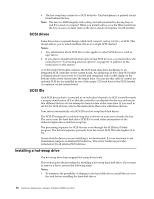
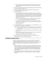
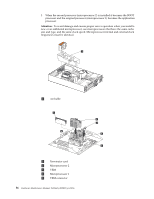
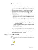
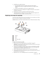
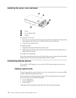
6 Microprocessor 2 connector To install an additional microprocessor: 1. Review the information in "Before you begin" on page 45. 2. Turn off the server and peripheral devices and disconnect all external cables and power cords; then remove the cover (see "Removing the cover and bezel" on page 47). 3. Remove the air baffle by grasping it at the sides and lifting it from the server. 4. Remove the terminator card from the microprocessor connector. Store the terminator card in a safe place in the static-protective package that your new microprocessor is shipped in; you will need to install it again, if you ever remove the microprocessor. 5. Install the microprocessor: a. Touch the static-protective package containing the new microprocessor to any unpainted metal surface on the server; then, remove the microprocessor from the package. b. Center the microprocessor over the microprocessor connector and carefully press the microprocessor into the connector. Note: To remove a microprocessor, pull upward on the microprocessor handle. 6. Install the VRM included in the microprocessor kit. Attention: When installing or replacing a VRM, use only a VRM specified for use with the Netfinity 4500R server. Use of other VRMs might cause your server to overheat. a. Center the VRM over the VRM connector. Make sure that the VRM is oriented and aligned correctly. b. Press the VRM into the connector. Note: If you remove the microprocessor later, remember to install the terminator card in the appropriate microprocessor connector and to remove the VRM. 7. Install the air baffle. Make sure the sides of the air baffle fit inside the brackets on the server. 8. If you have other options to install or remove, do so now; otherwise, go to "Installing the server cover and bezel" on page 60. Installing a hot-swap power supply Your server comes with one power supply. You can install an additional power supply. Note: You do not need to turn off the power to the server to install a hot-swap power supply. CAUTION: Installing options 57
-
 1
1 -
2
-
3
-
4
-
5
-
6
-
7
-
8
-
9
-
10
-
11
-
12
-
13
-
14
-
15
-
16
-
17
-
18
-
19
-
20
-
21
-
22
-
23
-
24
-
25
-
26
-
27
-
28
-
29
-
30
-
31
-
32
-
33
-
34
-
35
-
36
-
37
-
38
-
39
-
40
-
41
-
42
-
43
-
44
-
45
-
46
-
47
-
48
-
49
-
50
-
51
-
52
-
53
-
54
-
55
-
56
-
57
-
58
-
59
-
 60
60 -
 61
61 -
 62
62 -
 63
63 -
 64
64 -
 65
65 -
 66
66 -
 67
67 -
 68
68 -
 69
69 -
 70
70 -
71
-
72
-
73
-
74
-
75
-
76
-
77
-
78
-
79
-
80
-
81
-
82
-
83
-
84
-
85
-
86
-
87
-
88
-
89
-
90
-
91
-
92
-
93
-
94
-
95
-
96
-
97
-
98
-
99
-
100
-
101
-
102
-
103
-
104
-
105
-
106
-
107
-
108
-
109
-
110
-
111
-
112
-
113
-
114
-
115
-
116
-
117
-
118
-
119
-
120
-
121
-
122
-
123
-
124
-
125
-
126
-
127
-
128
-
129
-
130
-
131
-
132
-
133
-
134
-
135
-
136
-
137
-
138
-
139
-
140
-
141
-
142
-
143
-
144
-
145
-
146
-
147
-
148
-
149
-
150
-
151
-
152
-
153
-
154
-
155
-
156
-
157
-
158
-
159
-
160
-
161
-
162
-
163
-
164
-
165
-
166
-
167
-
168
-
169
-
170
-
171
-
172
-
173
-
174
-
175
-
176
-
177
-
178
-
179
-
180
-
181
-
182
-
183
-
184
-
185
-
186
-
187
-
188
-
189
-
190
-
191
-
192
 |
 |