IBM 4500R Hardware Maintenance Manual - Page 126
Information LED Panel, Diagnostics LED Panel
 |
UPC - 087944567837
View all IBM 4500R manuals
Add to My Manuals
Save this manual to your list of manuals |
Page 126 highlights
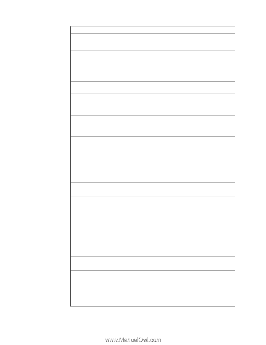
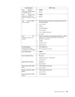
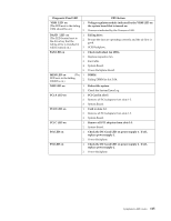
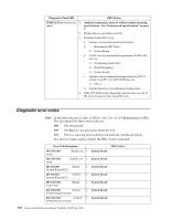
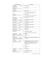
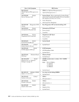
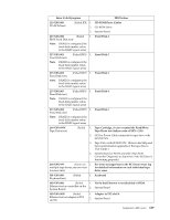
Error Code/Symptom FRU/Action 089-XXX-002 (Failed Optional Microprocessor test) 1. VRM 2 for Optional Microprocessor 2 2. Optional Microprocessor 2 165-XXX-000 (Failed Service Processor test) 1. System Board. Before replacing the System Board, ensure that System Board jumper J45 is not installed (the default) when the error occurs. 2. Power Backplane 3. Hot-Swap Drive Backplane 180-XXX-000 (Diagnostics LED 1. Run Diagnostic LED test for the failing LED. failure) 180-XXX-001 (Failed information LED panel test) 1. Information LED Panel 2. Power Switch 3. Assembly 180-XXX-002 (Failed Diagnostics LED Panel test) 1. Diagnostics LED Panel 2. Power Switch 3. Assembly 180-XXX-003 (Failed System Board LED test) 1. System Board 180-XXX-004 (Failed System Board LED test) 1. System Board 180-XXX-005 (Failed SCSI Backplane LED test) 1. SCSI Backplane 2. SCSI Backplane Cable 3. System Board 180-XXX-006 LED test) (Memory Board 1. Memory Board 2. System Board 201-XXX-0NN (Failed Memory test, see "Memory Settings" on page 33) 1. DIMM Location slots 1-4 where NN = DIMM location. Note: NN=1=DIMM 2 =2=DIMM 1 =3=DIMM 4 =4=DIMM 3 2. System Board 201-XXX-999 (Multiple DIMM 1. See error text for failing DIMMs failure, see error text) 2. System Board 202-XXX-001 System Cache test) (Failed 1. VRM 1 2. Microprocessor 1 202-XXX-002 (Failed System Cache test) 1. VRM 2 2. Microprocessor 2 206-XXX-000 (Failed Diskette Drive test) 1. Cable 2. Diskette Drive 3. System Board 118 Hardware Maintenance Manual: Netfinity 4500R Type 8656
-
 1
1 -
2
-
3
-
4
-
5
-
6
-
7
-
8
-
9
-
10
-
11
-
12
-
13
-
14
-
15
-
16
-
17
-
18
-
19
-
20
-
21
-
22
-
23
-
24
-
25
-
26
-
27
-
28
-
29
-
30
-
31
-
32
-
33
-
34
-
35
-
36
-
37
-
38
-
39
-
40
-
41
-
42
-
43
-
44
-
45
-
46
-
47
-
48
-
49
-
50
-
51
-
52
-
53
-
54
-
55
-
56
-
57
-
58
-
59
-
60
-
61
-
62
-
63
-
64
-
65
-
66
-
67
-
68
-
69
-
70
-
71
-
72
-
73
-
74
-
75
-
76
-
77
-
78
-
79
-
80
-
81
-
82
-
83
-
84
-
85
-
86
-
87
-
88
-
89
-
90
-
91
-
92
-
93
-
94
-
95
-
96
-
97
-
98
-
99
-
100
-
101
-
102
-
103
-
104
-
105
-
106
-
107
-
108
-
109
-
110
-
111
-
112
-
113
-
114
-
115
-
116
-
117
-
118
-
119
-
120
-
 121
121 -
 122
122 -
 123
123 -
 124
124 -
 125
125 -
 126
126 -
 127
127 -
 128
128 -
 129
129 -
 130
130 -
 131
131 -
132
-
133
-
134
-
135
-
136
-
137
-
138
-
139
-
140
-
141
-
142
-
143
-
144
-
145
-
146
-
147
-
148
-
149
-
150
-
151
-
152
-
153
-
154
-
155
-
156
-
157
-
158
-
159
-
160
-
161
-
162
-
163
-
164
-
165
-
166
-
167
-
168
-
169
-
170
-
171
-
172
-
173
-
174
-
175
-
176
-
177
-
178
-
179
-
180
-
181
-
182
-
183
-
184
-
185
-
186
-
187
-
188
-
189
-
190
-
191
-
192
 |
 |