IBM 4500R Hardware Maintenance Manual - Page 55
Removing the cover and bezel
 |
UPC - 087944567837
View all IBM 4500R manuals
Add to My Manuals
Save this manual to your list of manuals |
Page 55 highlights
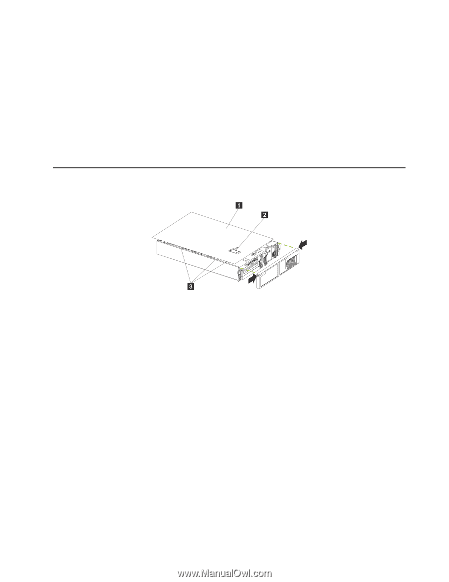
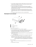
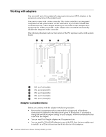
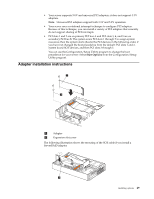
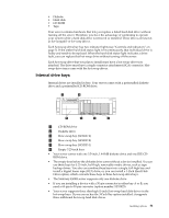
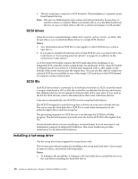
• Always handle components carefully. Handle adapters, the memory board, and memory modules (DIMMs) by the edges. Never touch any exposed circuitry. • Prevent others from touching components. • When you are installing a new option, touch the static-protective package containing the option to a metal expansion-slot screw or other unpainted metal surface on the server for at least two seconds. (This reduces static electricity from the package and from your body.) • When possible, remove the option and install it directly into the server without setting the option down. When this is not possible, place the static-protective package that the option comes in on a smooth, level surface and place the option on it. • Do not place the option on the server's covers or any metal surface. Removing the cover and bezel 1 Cover 2 Cover release latch 3 Flanges To remove the server top cover: 1. Review the information in "Before you begin" on page 45. 2. If you are planning to install or remove any part other than a hot-swap hard disk drive, hot-swap power supply, or hot-swap fan, turn off the server and all attached devices and disconnect all external cables and power cords. 3. Release the left and right side latches and pull the server out of the rack enclosure until both slide rails lock. Note: When the server is in the locked position, you can reach the cables on the back of the server. 4. Lift the cover-release latch and slide the top cover toward the rear of the server about 25 mm (1 inch). Lift the cover off the server and set the cover aside. Attention: For proper cooling and airflow, replace the cover before turning on the server. Operating the server for extended periods of time (over 30 minutes) with the cover removed might damage server components. To remove the bezel: 1. Press in on the top sides of the bezel and pull the bezel away from the server front. 2. Store the bezel in a safe place. Installing options 47
-
 1
1 -
2
-
3
-
4
-
5
-
6
-
7
-
8
-
9
-
10
-
11
-
12
-
13
-
14
-
15
-
16
-
17
-
18
-
19
-
20
-
21
-
22
-
23
-
24
-
25
-
26
-
27
-
28
-
29
-
30
-
31
-
32
-
33
-
34
-
35
-
36
-
37
-
38
-
39
-
40
-
41
-
42
-
43
-
44
-
45
-
46
-
47
-
48
-
49
-
 50
50 -
 51
51 -
 52
52 -
 53
53 -
 54
54 -
 55
55 -
 56
56 -
 57
57 -
 58
58 -
 59
59 -
 60
60 -
61
-
62
-
63
-
64
-
65
-
66
-
67
-
68
-
69
-
70
-
71
-
72
-
73
-
74
-
75
-
76
-
77
-
78
-
79
-
80
-
81
-
82
-
83
-
84
-
85
-
86
-
87
-
88
-
89
-
90
-
91
-
92
-
93
-
94
-
95
-
96
-
97
-
98
-
99
-
100
-
101
-
102
-
103
-
104
-
105
-
106
-
107
-
108
-
109
-
110
-
111
-
112
-
113
-
114
-
115
-
116
-
117
-
118
-
119
-
120
-
121
-
122
-
123
-
124
-
125
-
126
-
127
-
128
-
129
-
130
-
131
-
132
-
133
-
134
-
135
-
136
-
137
-
138
-
139
-
140
-
141
-
142
-
143
-
144
-
145
-
146
-
147
-
148
-
149
-
150
-
151
-
152
-
153
-
154
-
155
-
156
-
157
-
158
-
159
-
160
-
161
-
162
-
163
-
164
-
165
-
166
-
167
-
168
-
169
-
170
-
171
-
172
-
173
-
174
-
175
-
176
-
177
-
178
-
179
-
180
-
181
-
182
-
183
-
184
-
185
-
186
-
187
-
188
-
189
-
190
-
191
-
192
 |
 |