IBM 4500R Hardware Maintenance Manual - Page 48
System board layout, System board options connectors, Voltage regulator module 2 VRM2 U26
 |
UPC - 087944567837
View all IBM 4500R manuals
Add to My Manuals
Save this manual to your list of manuals |
Page 48 highlights
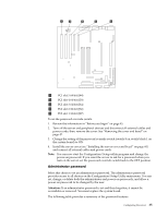
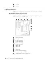
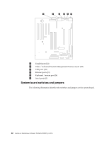
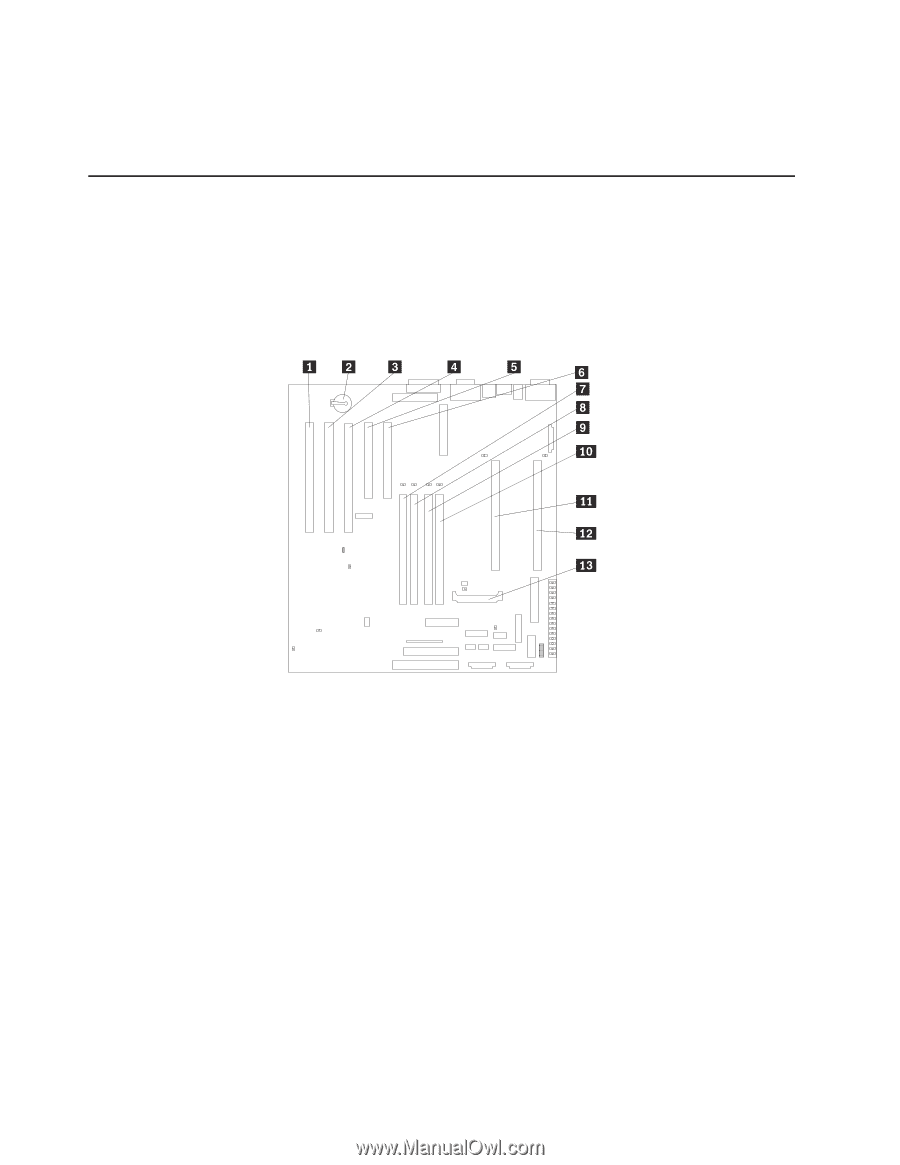
10 Air baffle 11 Rear fan System board layout The illustrations in the following sections show the components on the system board. System board options connectors The following illustration shows a layout of the system board and identifies systemboard connectors for user-installable options. 1 PCI slot 5 32-bit (J44) 2 Battery 3 PCI slot 4 32-bit (J39) 4 PCI slot 3 64-bit (J34) 5 PCI slot 2 64-bit (J32) 6 PCI slot 1 64-bit (J27) 7 DIMM 1 (J23) 8 DIMM 2 (J21) 9 DIMM 3 (J19) 10 DIMM 4 (J18) 11 Primary microprocessor (U17) 12 Secondary microprocessor (U3) 13 Voltage regulator module 2 (VRM2) (U26) 40 Hardware Maintenance Manual: Netfinity 4500R Type 8656
-
 1
1 -
2
-
3
-
4
-
5
-
6
-
7
-
8
-
9
-
10
-
11
-
12
-
13
-
14
-
15
-
16
-
17
-
18
-
19
-
20
-
21
-
22
-
23
-
24
-
25
-
26
-
27
-
28
-
29
-
30
-
31
-
32
-
33
-
34
-
35
-
36
-
37
-
38
-
39
-
40
-
41
-
42
-
 43
43 -
 44
44 -
 45
45 -
 46
46 -
 47
47 -
 48
48 -
 49
49 -
 50
50 -
 51
51 -
 52
52 -
 53
53 -
54
-
55
-
56
-
57
-
58
-
59
-
60
-
61
-
62
-
63
-
64
-
65
-
66
-
67
-
68
-
69
-
70
-
71
-
72
-
73
-
74
-
75
-
76
-
77
-
78
-
79
-
80
-
81
-
82
-
83
-
84
-
85
-
86
-
87
-
88
-
89
-
90
-
91
-
92
-
93
-
94
-
95
-
96
-
97
-
98
-
99
-
100
-
101
-
102
-
103
-
104
-
105
-
106
-
107
-
108
-
109
-
110
-
111
-
112
-
113
-
114
-
115
-
116
-
117
-
118
-
119
-
120
-
121
-
122
-
123
-
124
-
125
-
126
-
127
-
128
-
129
-
130
-
131
-
132
-
133
-
134
-
135
-
136
-
137
-
138
-
139
-
140
-
141
-
142
-
143
-
144
-
145
-
146
-
147
-
148
-
149
-
150
-
151
-
152
-
153
-
154
-
155
-
156
-
157
-
158
-
159
-
160
-
161
-
162
-
163
-
164
-
165
-
166
-
167
-
168
-
169
-
170
-
171
-
172
-
173
-
174
-
175
-
176
-
177
-
178
-
179
-
180
-
181
-
182
-
183
-
184
-
185
-
186
-
187
-
188
-
189
-
190
-
191
-
192
 |
 |
40
Hardware Maintenance Manual: Netfinity 4500R Type 8656
±
10
²
Air baffle
±
11
²
Rear fan
System board layout
The illustrations in the following sections show the components on the system board.
System board options connectors
The following illustration shows a layout of the system board and identifies system-
board connectors for user-installable options.
±
1
²
PCI slot 5 32-bit (J44)
±
2
²
Battery
±
3
²
PCI slot 4 32-bit (J39)
±
4
²
PCI slot 3 64-bit (J34)
±
5
²
PCI slot 2 64-bit (J32)
±
6
²
PCI slot 1 64-bit (J27)
±
7
²
DIMM 1 (J23)
±
8
²
DIMM 2 (J21)
±
9
²
DIMM 3 (J19)
±
10
²
DIMM 4 (J18)
±
11
²
Primary microprocessor (U17)
±
12
²
Secondary microprocessor (U3)
±
13
²
Voltage regulator module 2 (VRM2) (U26)