IBM 4500R Hardware Maintenance Manual - Page 81
Ethernet port connector, Advanced System Management ports, Cabling the Server
 |
UPC - 087944567837
View all IBM 4500R manuals
Add to My Manuals
Save this manual to your list of manuals |
Page 81 highlights
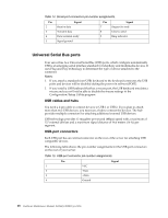
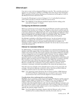
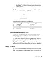
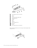
where d and path are the drive and path where the driver is located. This command causes the device driver to locate the primary adapter and switch the Ethernet traffic to it. Ethernet port connector The following table shows the pin-number assignments for the RJ-45 connector. These assignments apply to both 10BASE-T and 100BASE-TX devices. Table 16. Ethernet RJ-45 connector pin-number assignments.. Pin 1 2 3 4 Signal Transmit data+ Transmit dataReceive data+ Not connected Pin 5 6 7 8 Signal Not connected Receive data Not connected Not connected Advanced System Management ports Your server has three communication ports dedicated to the Netfinity Advanced System Management Processor. One port uses a standard D-shell serial-port connector, connector C. The other two ports, which are used for the RS-485 function, use a dual RJ-45 connector. You can attach a dedicated modem to the D-shell system-management connector on the rear of your server to communicate with the integrated Netfinity Advanced System Management Processor. The RS-485 function uses the RJ-45 system-management connectors. This function enables you to connect the Advanced System Management Processors of several rackmounted servers so that they can communicate with each other in half-duplex mode. Cabling the Server The following illustration shows input/output connectors and cable routing for the server. Note: The illustrations in this document might differ slightly from your hardware. Installing options 73
-
 1
1 -
2
-
3
-
4
-
5
-
6
-
7
-
8
-
9
-
10
-
11
-
12
-
13
-
14
-
15
-
16
-
17
-
18
-
19
-
20
-
21
-
22
-
23
-
24
-
25
-
26
-
27
-
28
-
29
-
30
-
31
-
32
-
33
-
34
-
35
-
36
-
37
-
38
-
39
-
40
-
41
-
42
-
43
-
44
-
45
-
46
-
47
-
48
-
49
-
50
-
51
-
52
-
53
-
54
-
55
-
56
-
57
-
58
-
59
-
60
-
61
-
62
-
63
-
64
-
65
-
66
-
67
-
68
-
69
-
70
-
71
-
72
-
73
-
74
-
75
-
 76
76 -
 77
77 -
 78
78 -
 79
79 -
 80
80 -
 81
81 -
 82
82 -
 83
83 -
 84
84 -
 85
85 -
 86
86 -
87
-
88
-
89
-
90
-
91
-
92
-
93
-
94
-
95
-
96
-
97
-
98
-
99
-
100
-
101
-
102
-
103
-
104
-
105
-
106
-
107
-
108
-
109
-
110
-
111
-
112
-
113
-
114
-
115
-
116
-
117
-
118
-
119
-
120
-
121
-
122
-
123
-
124
-
125
-
126
-
127
-
128
-
129
-
130
-
131
-
132
-
133
-
134
-
135
-
136
-
137
-
138
-
139
-
140
-
141
-
142
-
143
-
144
-
145
-
146
-
147
-
148
-
149
-
150
-
151
-
152
-
153
-
154
-
155
-
156
-
157
-
158
-
159
-
160
-
161
-
162
-
163
-
164
-
165
-
166
-
167
-
168
-
169
-
170
-
171
-
172
-
173
-
174
-
175
-
176
-
177
-
178
-
179
-
180
-
181
-
182
-
183
-
184
-
185
-
186
-
187
-
188
-
189
-
190
-
191
-
192
 |
 |