IBM 4500R Hardware Maintenance Manual - Page 53
Before you begin, Description, PCI 1, DASD1
 |
UPC - 087944567837
View all IBM 4500R manuals
Add to My Manuals
Save this manual to your list of manuals |
Page 53 highlights
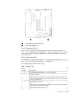
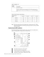
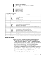
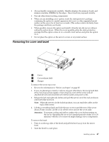
5 Diagnostics panel (See Table 6) 6 Advanced System Management Processor error (CR70) 7 Power-on (CR56) 8 DIMM1 failure (CR21) 9 DIMM2 failure (CR28) 10 DIMM3 ailure (CR18) 11 DIMM4 failure (CR20) Table 9. Diagnostics panel LEDs. CR 29 30 31 32 33 34 22 23 24 25 26 27 58 53 57 LED PS1 PS2 PS3 NON OVER NMI TEMP FAN MEM CPU PCI 1 PCI 2 VRM DASD1 DASD2 Description Power supply 1 failure. Power supply 2 failure. Not used. Non-redundant power. Overspecification. The system has exceeded the power capibilities of the installed power supply units. Non-maskable-interrupt occurred. System temperature exceeded maximum rating. A fan failed or is operating slowly. Memory failure. One or more dual in-line memory modules (DIMMS) failed. Microprocessor failure. One or both microprocessors failed. Error on primary PCI channel (A) or system board. Error on secondary PCI channel (B) or system board. Error on voltage regulator module or on integrated voltage regulator. SCSI bus A failure. The SCSI backplane (if any) or a device connected to SCSI bus A failed. SCSI bus B failure. The SCSI hot-swap disk drive backplane on SCSI bus B failed. Before you begin Before you begin to install options in your server, read the following information: • Become familiar with the safety and handling guidelines specified under "Working inside a server with power on" on page 46, "Handling static-sensitive devices" on page 46, and read "Safety information" on page 141. These guidelines will help you work safely while working with your server or options. • You do not need to turn off the server to install or replace hot-swap power supplies, hot-swap drives, hot-swap fans, or hot-plug PCI adapters. • The orange color on components and labels in your server indentifies hot-swap or hot-plug components. This means that you can install or remove the component while the system is running, provided that your system is configured to support this function. For complete details about installing or removing a hot-swap or hotplug component, see the information provided in this chapter. • The blue color on components and labels indentifies touch points where a component can be gripped, a latch moved, and so on. Installing options 45
-
 1
1 -
2
-
3
-
4
-
5
-
6
-
7
-
8
-
9
-
10
-
11
-
12
-
13
-
14
-
15
-
16
-
17
-
18
-
19
-
20
-
21
-
22
-
23
-
24
-
25
-
26
-
27
-
28
-
29
-
30
-
31
-
32
-
33
-
34
-
35
-
36
-
37
-
38
-
39
-
40
-
41
-
42
-
43
-
44
-
45
-
46
-
47
-
 48
48 -
 49
49 -
 50
50 -
 51
51 -
 52
52 -
 53
53 -
 54
54 -
 55
55 -
 56
56 -
 57
57 -
 58
58 -
59
-
60
-
61
-
62
-
63
-
64
-
65
-
66
-
67
-
68
-
69
-
70
-
71
-
72
-
73
-
74
-
75
-
76
-
77
-
78
-
79
-
80
-
81
-
82
-
83
-
84
-
85
-
86
-
87
-
88
-
89
-
90
-
91
-
92
-
93
-
94
-
95
-
96
-
97
-
98
-
99
-
100
-
101
-
102
-
103
-
104
-
105
-
106
-
107
-
108
-
109
-
110
-
111
-
112
-
113
-
114
-
115
-
116
-
117
-
118
-
119
-
120
-
121
-
122
-
123
-
124
-
125
-
126
-
127
-
128
-
129
-
130
-
131
-
132
-
133
-
134
-
135
-
136
-
137
-
138
-
139
-
140
-
141
-
142
-
143
-
144
-
145
-
146
-
147
-
148
-
149
-
150
-
151
-
152
-
153
-
154
-
155
-
156
-
157
-
158
-
159
-
160
-
161
-
162
-
163
-
164
-
165
-
166
-
167
-
168
-
169
-
170
-
171
-
172
-
173
-
174
-
175
-
176
-
177
-
178
-
179
-
180
-
181
-
182
-
183
-
184
-
185
-
186
-
187
-
188
-
189
-
190
-
191
-
192
 |
 |