IBM 4500R Hardware Maintenance Manual - Page 52
System board LED locations, Microprocessor, speed, Switch 1, number, Description
 |
UPC - 087944567837
View all IBM 4500R manuals
Add to My Manuals
Save this manual to your list of manuals |
Page 52 highlights
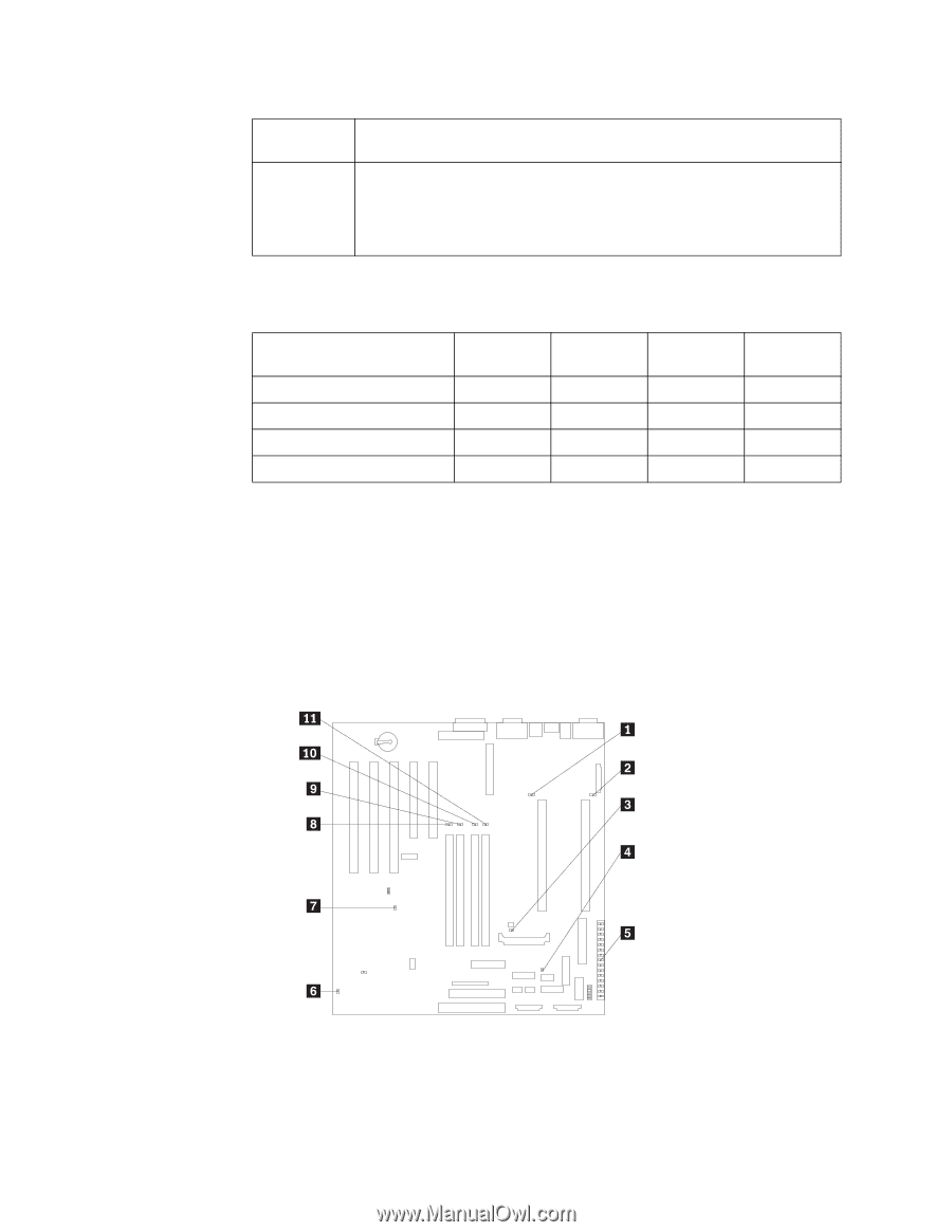
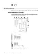
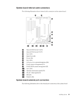
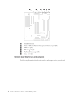
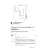
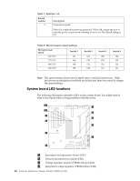
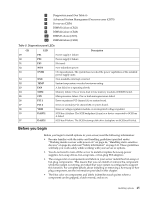
Table 7. Switches 1-8. Switch number 8 Description Password override. When On, bypass the power-on password. When Off, require the user to enter the power-on password at startup, if one is set. The default setting is Off. Table 8. Microprocessor speed settings. Microprocessor speed 667/133 733/133 800/133 866/133 Switch 1 On On Off Off Switch 2 On Off On Off Switch 3 Off Off On On Switch 4 Off Off On On Note: The speed settings shown above apply only to unlocked processors. If the processors are production level they are locked and there is no need to change the speed settings. System board LED locations The following illustration identifies LEDs on the system board. You might need to refer to this figure when solving problems with the server. 1 Secondary microprocessor failure (CR7) 2 Primary microprocessor failure (CR1) 3 Voltage regulator module (VRM2) failure (CR16) 4 Integrated voltage regulator (VRM1) failure (CR4) 44 Hardware Maintenance Manual: Netfinity 4500R Type 8656
-
 1
1 -
2
-
3
-
4
-
5
-
6
-
7
-
8
-
9
-
10
-
11
-
12
-
13
-
14
-
15
-
16
-
17
-
18
-
19
-
20
-
21
-
22
-
23
-
24
-
25
-
26
-
27
-
28
-
29
-
30
-
31
-
32
-
33
-
34
-
35
-
36
-
37
-
38
-
39
-
40
-
41
-
42
-
43
-
44
-
45
-
46
-
 47
47 -
 48
48 -
 49
49 -
 50
50 -
 51
51 -
 52
52 -
 53
53 -
 54
54 -
 55
55 -
 56
56 -
 57
57 -
58
-
59
-
60
-
61
-
62
-
63
-
64
-
65
-
66
-
67
-
68
-
69
-
70
-
71
-
72
-
73
-
74
-
75
-
76
-
77
-
78
-
79
-
80
-
81
-
82
-
83
-
84
-
85
-
86
-
87
-
88
-
89
-
90
-
91
-
92
-
93
-
94
-
95
-
96
-
97
-
98
-
99
-
100
-
101
-
102
-
103
-
104
-
105
-
106
-
107
-
108
-
109
-
110
-
111
-
112
-
113
-
114
-
115
-
116
-
117
-
118
-
119
-
120
-
121
-
122
-
123
-
124
-
125
-
126
-
127
-
128
-
129
-
130
-
131
-
132
-
133
-
134
-
135
-
136
-
137
-
138
-
139
-
140
-
141
-
142
-
143
-
144
-
145
-
146
-
147
-
148
-
149
-
150
-
151
-
152
-
153
-
154
-
155
-
156
-
157
-
158
-
159
-
160
-
161
-
162
-
163
-
164
-
165
-
166
-
167
-
168
-
169
-
170
-
171
-
172
-
173
-
174
-
175
-
176
-
177
-
178
-
179
-
180
-
181
-
182
-
183
-
184
-
185
-
186
-
187
-
188
-
189
-
190
-
191
-
192
 |
 |