Mackie D8B Owners Manual - Page 131
Using the Digital 8•Bus with ADATs, Click on Digital I/O to open the Digital I/O
 |
View all Mackie D8B manuals
Add to My Manuals
Save this manual to your list of manuals |
Page 131 highlights
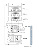
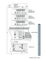
OK, so we fibbed a little. You can use PDI•8 cards in the D8B without a Clock I/O card installed, but doing so requires that you enable sample rate conversion on both the D8B and the HDR24/96 in lieu of word clock synchronization. Sample rate conversion results in a 4-bit loss in sample resolution that may degrade the quality of the sound slightly. On the positive side, you don't need a Clock I/O card! Using the Digital 8•Bus with ADATs This is a simple setup. It works well and is easy to configure. However, it has some limitations. Without a MTC sync source there's no way for the Digital 8•Bus to time-reference snapshot or dynamic automation. As long as automation isn't a consideration, this setup is clean and efficient. Cabling and Hookup 1. Connect a fiber optic cable between the ADAT's lightpipe output and the D8B's lightpipe input. Likewise, connect the D8B's lightpipe output to the ADAT's lightpipe input. (A DIO•8 or OPT•8 lightpipe card must be installed in the D8B to gain access to the ADAT digital tape inputs and outputs.) 2. When using multiple ADATs, connect SYNC OUT from the master ADAT to SYNC IN of the first slave, then from SYNC OUT of the first slave to SYNC IN of the second slave, and so on. Settings D8B 1. Open the Setup window. 2. Click on "Digital I/O" to open the Digital I/O dialog box. 3. Click on each Tape Input and Output box and select ADAT for each DIO•8 card installed. 4. Set "Samplerate" to match the sample rate of the formatted ADAT tapes (typically 48kHz or 44.1kHz). ADATs 1. Select DIGITAL IN on the ADAT front panel. Modular Digital Multitrack CLOCK EXT 48K INPUT MON INPUT DIGITAL INPUT SELECT DIGITAL INPUT TRACK COPY INPUT MONITOR ALL INPUT AUTO INPUT Note: When powering up, turn the Digital 8•Bus on first, then turn the ADATs on. D8B Manual • Chapter 4 • page 125
-
 1
1 -
2
-
3
-
4
-
5
-
6
-
7
-
8
-
9
-
10
-
11
-
12
-
13
-
14
-
15
-
16
-
17
-
18
-
19
-
20
-
21
-
22
-
23
-
24
-
25
-
26
-
27
-
28
-
29
-
30
-
31
-
32
-
33
-
34
-
35
-
36
-
37
-
38
-
39
-
40
-
41
-
42
-
43
-
44
-
45
-
46
-
47
-
48
-
49
-
50
-
51
-
52
-
53
-
54
-
55
-
56
-
57
-
58
-
59
-
60
-
61
-
62
-
63
-
64
-
65
-
66
-
67
-
68
-
69
-
70
-
71
-
72
-
73
-
74
-
75
-
76
-
77
-
78
-
79
-
80
-
81
-
82
-
83
-
84
-
85
-
86
-
87
-
88
-
89
-
90
-
91
-
92
-
93
-
94
-
95
-
96
-
97
-
98
-
99
-
100
-
101
-
102
-
103
-
104
-
105
-
106
-
107
-
108
-
109
-
110
-
111
-
112
-
113
-
114
-
115
-
116
-
117
-
118
-
119
-
120
-
121
-
122
-
123
-
124
-
125
-
 126
126 -
 127
127 -
 128
128 -
 129
129 -
 130
130 -
 131
131 -
 132
132 -
 133
133 -
 134
134 -
 135
135 -
 136
136 -
137
-
138
-
139
-
140
-
141
-
142
-
143
-
144
-
145
-
146
-
147
-
148
-
149
-
150
-
151
-
152
-
153
-
154
-
155
-
156
-
157
-
158
-
159
-
160
-
161
-
162
-
163
-
164
-
165
-
166
-
167
-
168
-
169
-
170
-
171
-
172
-
173
-
174
-
175
-
176
-
177
-
178
-
179
-
180
-
181
-
182
-
183
-
184
-
185
-
186
-
187
-
188
-
189
-
190
-
191
-
192
-
193
-
194
-
195
-
196
-
197
-
198
 |
 |
