Mackie D8B Owners Manual - Page 18
Keep Close Track of These Concepts, Basic Mixdown Setup - digital mixing console
 |
View all Mackie D8B manuals
Add to My Manuals
Save this manual to your list of manuals |
Page 18 highlights
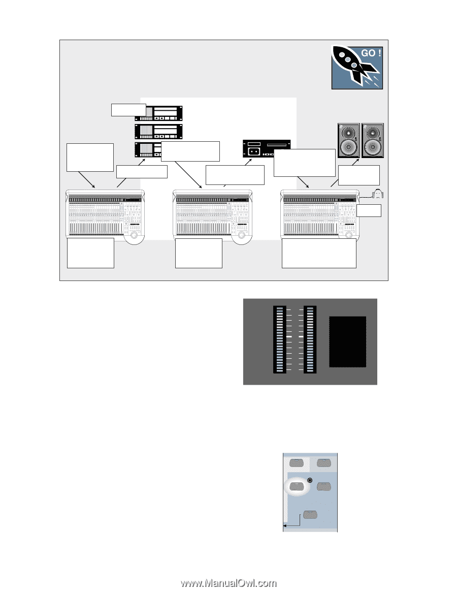
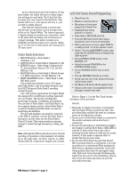
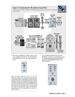
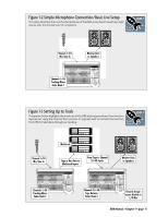
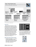
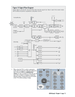
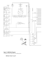
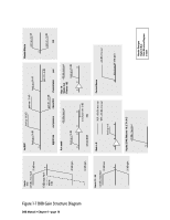
Figure 1-4 Basic Mixdown Setup This is a basic mixdown setup. Live Mic/Line input source might be used for any audio source: live vocals, instruments, or effects returns. FAST TRACK Multitrack Outboard Effects, MIDI Gear, Live Room Mics, etc. From Tape to Channel 25-48 Inputs Tape or Bus Outs From Master Out to Mixdown Recorder From Mix Playback to 2-Track Input (Analog or Digital) Monitor Outs to Speakers Phones Channels 1-24 Tracking Mixer Fader Bank 1 Channels 25-48 Monitor Tape Fader Bank 2 Monitor Mixdown Machine at CONTROL ROOM in the Master Section Use this diagram for troubleshooting! Signal Flow The previous diagrams help create an accurate mental image of how the D8B functions. The signal flow diagram in Figure 1-5 (on the next page) looks more closely at the actual path the signal takes from a point of origin to a chosen destination. This is a simplified flow-diagram designed to provide a "bird'seye" view. Follow the signal from left to right. Notice the first thing the signal encounters, after the analog inputs (including the analog trim), is the analog-todigital converter. The audio remains in the digital domain from that point until it finally converts back to analog at the main outputs, bus outputs, and external aux sends. Simply follow the arrows to discover the path-you never know where you might end up. For a more detailed block diagram of the D8B signal path refer to Figure 1-6. Keep Close Track of These Concepts 1. The Channel Select Display, next to the Master L/R meters, always displays the currently selected channel number no matter which Fader Bank is selected. If an adjustment is required in the Fat Channel, verify that the channel you intend to adjust is displayed here. OL 2 4 7 10 15 20 25 30 35 40 50 LEFT RIGHT CHANNEL 33 2. Be sure you verify the Bank Selection whenever you need to make a change. At first it's easy to forget to check the Fader Bank status. However, once you've adjusted to the layered consoles, maneuvering throughout the entire console will become second nature. MASTERS 1-24 SHIFT 25-48 MIC/LINE (TRACK) TAPE IN (MONITOR) 49-72 EFFECTS BANK SELECT D8B Manual • Chapter 1 • page 12
-
 1
1 -
2
-
3
-
4
-
5
-
6
-
7
-
8
-
9
-
10
-
11
-
12
-
 13
13 -
 14
14 -
 15
15 -
 16
16 -
 17
17 -
 18
18 -
 19
19 -
 20
20 -
 21
21 -
 22
22 -
 23
23 -
24
-
25
-
26
-
27
-
28
-
29
-
30
-
31
-
32
-
33
-
34
-
35
-
36
-
37
-
38
-
39
-
40
-
41
-
42
-
43
-
44
-
45
-
46
-
47
-
48
-
49
-
50
-
51
-
52
-
53
-
54
-
55
-
56
-
57
-
58
-
59
-
60
-
61
-
62
-
63
-
64
-
65
-
66
-
67
-
68
-
69
-
70
-
71
-
72
-
73
-
74
-
75
-
76
-
77
-
78
-
79
-
80
-
81
-
82
-
83
-
84
-
85
-
86
-
87
-
88
-
89
-
90
-
91
-
92
-
93
-
94
-
95
-
96
-
97
-
98
-
99
-
100
-
101
-
102
-
103
-
104
-
105
-
106
-
107
-
108
-
109
-
110
-
111
-
112
-
113
-
114
-
115
-
116
-
117
-
118
-
119
-
120
-
121
-
122
-
123
-
124
-
125
-
126
-
127
-
128
-
129
-
130
-
131
-
132
-
133
-
134
-
135
-
136
-
137
-
138
-
139
-
140
-
141
-
142
-
143
-
144
-
145
-
146
-
147
-
148
-
149
-
150
-
151
-
152
-
153
-
154
-
155
-
156
-
157
-
158
-
159
-
160
-
161
-
162
-
163
-
164
-
165
-
166
-
167
-
168
-
169
-
170
-
171
-
172
-
173
-
174
-
175
-
176
-
177
-
178
-
179
-
180
-
181
-
182
-
183
-
184
-
185
-
186
-
187
-
188
-
189
-
190
-
191
-
192
-
193
-
194
-
195
-
196
-
197
-
198
 |
 |