Mackie D8B Owners Manual - Page 32
Control Surface Functions, Channel Strip - recording digital mixer
 |
View all Mackie D8B manuals
Add to My Manuals
Save this manual to your list of manuals |
Page 32 highlights
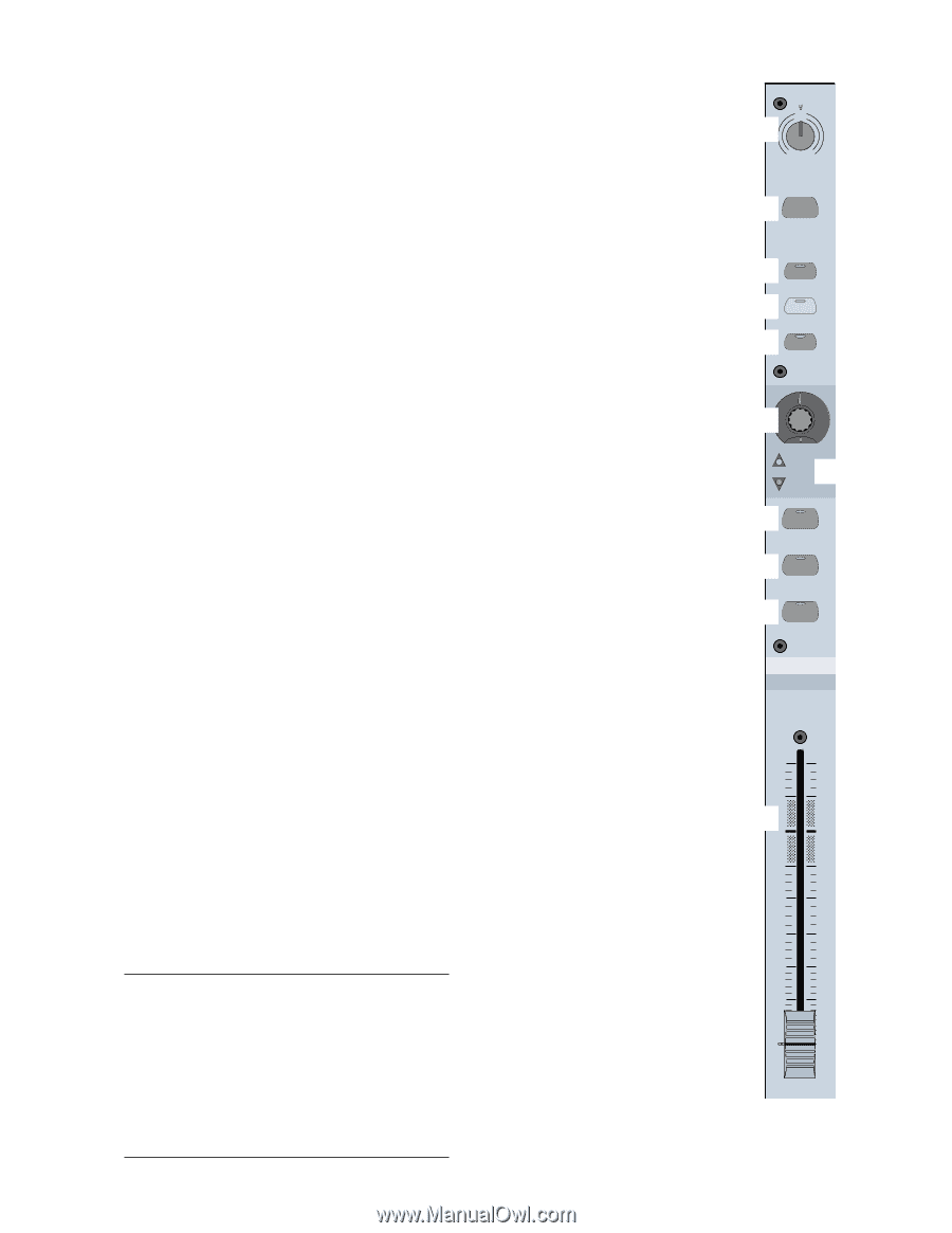
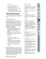
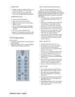
6 Ethernet Port • Accepts an RJ45 telco connector. • Connects to PC/Mac for FTP file transfer through a network or peer-to-peer. • Can be used to make peer-to-peer connections with other Digital 8•Bus consoles. • Use CAT5 for standard network FTP connections; use crossover CAT5 for peer-to-peer connections. Control Surface Functions We'll divide the D8B control surface into two sections, the Channel Strip section and the Master section. Channel Strip Section The channel strip on the Digital 8•Bus is very much like the channel strip on an analog mixer. Each channel offers the same set of controls, with a few exceptions. Even with a brief overview of each control, you'll find your understanding of the digital mixing concept closely related to what you already know about analog mixers-that's the beauty of this console design. • There are 24 channel strips. • There are four layers (Fader Banks) of feature sets: MIC/LINE (1-24), TAPE IN (25-48), EFFECTS (49-72), and MASTERS. • Channels 1-12 have both mic and line input capabilities. • Channels 13-24 have line input capabilities only. • Channels 25-48 receive signal only from the I/O card inputs. 1 Trim Level • At the top of each channel strip • The Trim Level controls only input levels for channels 1-24. • Regardless of bank selection, trims are active and available for channel inputs 1-24. This is handy for tweaking without having to switch banks. • Used to adjust and optimize input levels. • This control is one of the few not written in a snapshot. Note: The TRIM levels at the top of each of the 24 channel strips and the MIC buttons at the top of the first 12 channel strips are not written into automation or snapshots. Careful notes as to their status should be manually archived-as in written down-for future reference. However, if TRIMs are all left at unity gain- or at least left untouched-throughout the entire session, the console is capable of perfect, total recall! We highly recommend this technique. 2 Mic/Line Button • On channels 1-12 only. • This button selects between the Mic In- put (XLR) and the Line Input (1/4" TRS). • Up position selects the line input (1/4" TRS). • Down position selects the microphone input (XLR). 1 TRIM LINE MIC 0 60 -20dB +40dB 12 2 MIC 3 REC/RDY 3 REC/RDY 4 • The Record Ready button arms the cor- ASSIGN responding tape track to record. 5 • Communicates via MMC (MIDI Machine WRITE Control). 4 Assign 6 • Routes audio to output buses 1-8. • Routes audio to the Master L-R bus. • Assigns the selected channel to the 12 7 36 channel strip's corresponding tape track for recording. For example, after select- 8 SELECT ing ROUTE TO TAPE in the ASSIGNMENT section, press SELECT on channel 2, then press the ASSIGN 9 SOLO button on channel 12 to route the signal from channel 2 to tape track 12. bl MUTE 5 Write • Manually enables a channel for recording to automation. • Blinks when on standby; solid when active. • Automatically lights when Auto Touch automation has been activated. 6 Channel V-Pot MIDI 4 FX 12 12 36 dB 10 5 • A multifunctional digital control and bm level display. U • Controls channel pan when PAN is se- lected in the Master V-Pot section (just 5 to the right of channel 24). 10 • Controls Aux send levels when Aux 1-12 is selected in the AUX section (just 20 above the Master V-Pot). • Controls panning between stereo Auxes 30 9/10 and 11/12 when PAN is selected below either send. 40 50 • Controls channel Level to Tape and Digi- 60 tal Trim whenever they're selected (immediately above Aux 1 and 2 select buttons). • Displays return fader levels (Bank 2) when Level to Tape follows faders. D8B Manual • Chapter 2 • page 26
-
 1
1 -
2
-
3
-
4
-
5
-
6
-
7
-
8
-
9
-
10
-
11
-
12
-
13
-
14
-
15
-
16
-
17
-
18
-
19
-
20
-
21
-
22
-
23
-
24
-
25
-
26
-
 27
27 -
 28
28 -
 29
29 -
 30
30 -
 31
31 -
 32
32 -
 33
33 -
 34
34 -
 35
35 -
 36
36 -
 37
37 -
38
-
39
-
40
-
41
-
42
-
43
-
44
-
45
-
46
-
47
-
48
-
49
-
50
-
51
-
52
-
53
-
54
-
55
-
56
-
57
-
58
-
59
-
60
-
61
-
62
-
63
-
64
-
65
-
66
-
67
-
68
-
69
-
70
-
71
-
72
-
73
-
74
-
75
-
76
-
77
-
78
-
79
-
80
-
81
-
82
-
83
-
84
-
85
-
86
-
87
-
88
-
89
-
90
-
91
-
92
-
93
-
94
-
95
-
96
-
97
-
98
-
99
-
100
-
101
-
102
-
103
-
104
-
105
-
106
-
107
-
108
-
109
-
110
-
111
-
112
-
113
-
114
-
115
-
116
-
117
-
118
-
119
-
120
-
121
-
122
-
123
-
124
-
125
-
126
-
127
-
128
-
129
-
130
-
131
-
132
-
133
-
134
-
135
-
136
-
137
-
138
-
139
-
140
-
141
-
142
-
143
-
144
-
145
-
146
-
147
-
148
-
149
-
150
-
151
-
152
-
153
-
154
-
155
-
156
-
157
-
158
-
159
-
160
-
161
-
162
-
163
-
164
-
165
-
166
-
167
-
168
-
169
-
170
-
171
-
172
-
173
-
174
-
175
-
176
-
177
-
178
-
179
-
180
-
181
-
182
-
183
-
184
-
185
-
186
-
187
-
188
-
189
-
190
-
191
-
192
-
193
-
194
-
195
-
196
-
197
-
198
 |
 |