Mackie D8B Owners Manual - Page 29
Master Input/Output ALT I/O Card Slot, The Clock I/O Card, The Digital I/O Card 2-track - digital 8 bus mixing console
 |
View all Mackie D8B manuals
Add to My Manuals
Save this manual to your list of manuals |
Page 29 highlights
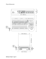
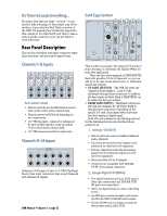
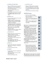
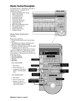
3 ADAT Optical (OPT•8) • Two digital ADAT optical (fiber optic) connections. • Each card offers I/O for 8 channels. 4 AES/EBU (PDI•8) • One 25-pin D-sub connector in digital AES/EBU format. • Each card offers I/O for 8 channels. 5 ALT I/O Card Slot • Separate input/output card slot offering 8 more ins and outs. • Holds any card: AIO•8, DIO•8, OPT•8, or PDI•8. • Inputs show up at RETURNS faders (channels 65-72). • Outputs are assignable to either the 8 bus outputs (BUS 1-8), the 12 Aux Sends (AUX 1-12), or the MASTER L-R outputs. • Assignments are made in the Digital I/O menu. 6 The Clock I/O Card • Provides word clock in and out to connect with other digital equipment. • For use as a master or slave clock source. • Supports 48kHz and 44.1kHz internal sample rates, with vari-speed capabilities. • Supports external sample rates between 32kHz and 50kHz. Note: The Apogee Clock I/O card replaces the standard clock card that is shipped in the SYNC slot with the D8B. 7 The Digital I/O Card (2-track) • AES/EBU digital I/O. Stereo interconnect for master record machine. Input is connected to DIGITAL 1 in the CONTROL ROOM monitor section. • S/PDIF digital I/O. Input is connected to DIGITAL 2 in the CONTROL ROOM monitor section. • Same source output as MASTER L-R. 8 Digital Effects Card Slots • Room for four separate effects cards. • MFX - Mackie Effects card with two stereo processors. • UFX - Universal DSP engine with functions dependent on specific plug-in effects. Each card is capable of four discrete mono, two stereo, or one stereo and two mono effects. • L-R Mix, Channel Pre or Post Insert, Buses 1-8, and Plugin Chain, in addition to the Aux sends 1-12, internally route to the four card locations. • Using the configurable plug-in architecture, insert plug-in capability is available for channels 1-48 (Pre- and Post-DSP), Buses 1-8, and Main Mix L-R. • Effects return to the main L-R mix at Fader Bank 3 via FX 1-16. Reminder: Power down the system before installing any cards! Master Input/Output Section bl BUS OUT 1-8 & SURROUND OUT 9 L R MASTER OUT LR bm CR MAIN LR CR NEAR FIELD LR MASTER OUT 2 TRACK IN A LR br 2 TRACK IN B LR bn PHONES 1 PHONES 2 bo STUDIO OUT LR 2 TRACK IN C LR bp bq PUNCH I/O TALKBACK 9 MASTER OUTputs (1/4" TRS and XLR) • Fed from the Master L/R fader on the console surface. • Both sets deliver balanced line-level signals. However, the TRS Master Outputs also provide unbalanced line-level signals. • Post fader, DSP, and D/A converter. bl BUS OUT 1-8 (SURROUND OUT) • 25-pin D-sub connector provides eight balanced line-level outputs. • Any channel (1-48), internal effects return, or ALT IN can be assigned to one or more bus outputs. • In Stereo Mode: Output level is controlled by the BUS 1-8 MASTERS (Fader Bank 4). • In Surround Mode: Output level is controlled by the Surround Monitor Level controls in the Surround window. D8B Manual • Chapter 2 • page 23
-
 1
1 -
2
-
3
-
4
-
5
-
6
-
7
-
8
-
9
-
10
-
11
-
12
-
13
-
14
-
15
-
16
-
17
-
18
-
19
-
20
-
21
-
22
-
23
-
 24
24 -
 25
25 -
 26
26 -
 27
27 -
 28
28 -
 29
29 -
 30
30 -
 31
31 -
 32
32 -
 33
33 -
 34
34 -
35
-
36
-
37
-
38
-
39
-
40
-
41
-
42
-
43
-
44
-
45
-
46
-
47
-
48
-
49
-
50
-
51
-
52
-
53
-
54
-
55
-
56
-
57
-
58
-
59
-
60
-
61
-
62
-
63
-
64
-
65
-
66
-
67
-
68
-
69
-
70
-
71
-
72
-
73
-
74
-
75
-
76
-
77
-
78
-
79
-
80
-
81
-
82
-
83
-
84
-
85
-
86
-
87
-
88
-
89
-
90
-
91
-
92
-
93
-
94
-
95
-
96
-
97
-
98
-
99
-
100
-
101
-
102
-
103
-
104
-
105
-
106
-
107
-
108
-
109
-
110
-
111
-
112
-
113
-
114
-
115
-
116
-
117
-
118
-
119
-
120
-
121
-
122
-
123
-
124
-
125
-
126
-
127
-
128
-
129
-
130
-
131
-
132
-
133
-
134
-
135
-
136
-
137
-
138
-
139
-
140
-
141
-
142
-
143
-
144
-
145
-
146
-
147
-
148
-
149
-
150
-
151
-
152
-
153
-
154
-
155
-
156
-
157
-
158
-
159
-
160
-
161
-
162
-
163
-
164
-
165
-
166
-
167
-
168
-
169
-
170
-
171
-
172
-
173
-
174
-
175
-
176
-
177
-
178
-
179
-
180
-
181
-
182
-
183
-
184
-
185
-
186
-
187
-
188
-
189
-
190
-
191
-
192
-
193
-
194
-
195
-
196
-
197
-
198
 |
 |
