Mackie D8B Owners Manual - Page 19
Signal-Flow Diagram, V-Pot is a multifunction, control
 |
View all Mackie D8B manuals
Add to My Manuals
Save this manual to your list of manuals |
Page 19 highlights
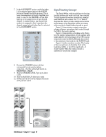
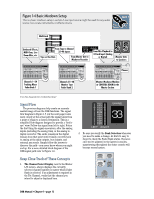
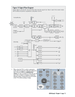
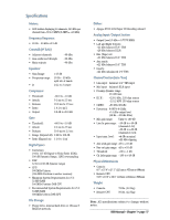
Figure 1-5 Signal-Flow Diagram Simply begin at the far left star and follow the route the signal must take to reach the master output. DSP includes all dynamics, equalization, and phase controls. Tracking/Routing Channel Meter Analog Inputs CH 1-24 Pre-DSP Insert Post-DSP Insert Analog to Digital Converter DSP (EQ, Comp, Gate, etc.) Level to Tape Channel Fader Pre Optional Tape I/O Card Main Inserts R L To Tape Outputs Channel Pan Post Bus Assign L Master L/R Fader R Bus Inserts Bus Master Bus 1-8 AES/EBU Out S/PDIF Out Digital to Analog Converter Main Out Digital to Analog Converter Bus 1-8 Outputs Monitoring AES/EBU S/PDIF 2 TRK A 2 TRK B 2 TRK C Aux Send Level Master Aux Send Level From L/R Out To FX Returns (Ch. 49-64), L or R Main Inserts, Channel Pre or Post-DSP Inserts, or Bus 1-8 DAC DAC Control Room Select Internal FX From Aux Sends 1 - 8, L or R Main Insert, Channel Pre or Post-DSP Insert, Plugin Chain, or Bus 1-8 Main L/R Meter Near Field Speaker Level Main Speaker Level Studio Level Auxes 9/10 Auxes 11/12 Cue Mix 1 Level Cue Mix 2 Level Digital to Analog Converter Aux Sends Lake Sammamish 6 miles CR Nearfield Out CR Main Out Studio Out Phones 1 Out Phones 2 Out 3. When using the V-Pot to adjust a parameter, make sure it's assigned to make the change you need. Since the V-Pot is a multifunction control, it's easy to assume it's doing the job you want when it might be changing a completely different setting. Intentionally check the status of the V-Pot before making a change. AUX 9-10 PAN AUX 11-12 PAN MASTER PAN SOLO 1-24 LEVEL TO TAPE 1-48 DIGITAL TRIM AUX 1 AUX 2 AUX 3 AUX 4 AUX 5 AUX 6 AUX 7 AUX 8 D8B Manual • Chapter 1 • page 13
-
 1
1 -
2
-
3
-
4
-
5
-
6
-
7
-
8
-
9
-
10
-
11
-
12
-
13
-
 14
14 -
 15
15 -
 16
16 -
 17
17 -
 18
18 -
 19
19 -
 20
20 -
 21
21 -
 22
22 -
 23
23 -
 24
24 -
25
-
26
-
27
-
28
-
29
-
30
-
31
-
32
-
33
-
34
-
35
-
36
-
37
-
38
-
39
-
40
-
41
-
42
-
43
-
44
-
45
-
46
-
47
-
48
-
49
-
50
-
51
-
52
-
53
-
54
-
55
-
56
-
57
-
58
-
59
-
60
-
61
-
62
-
63
-
64
-
65
-
66
-
67
-
68
-
69
-
70
-
71
-
72
-
73
-
74
-
75
-
76
-
77
-
78
-
79
-
80
-
81
-
82
-
83
-
84
-
85
-
86
-
87
-
88
-
89
-
90
-
91
-
92
-
93
-
94
-
95
-
96
-
97
-
98
-
99
-
100
-
101
-
102
-
103
-
104
-
105
-
106
-
107
-
108
-
109
-
110
-
111
-
112
-
113
-
114
-
115
-
116
-
117
-
118
-
119
-
120
-
121
-
122
-
123
-
124
-
125
-
126
-
127
-
128
-
129
-
130
-
131
-
132
-
133
-
134
-
135
-
136
-
137
-
138
-
139
-
140
-
141
-
142
-
143
-
144
-
145
-
146
-
147
-
148
-
149
-
150
-
151
-
152
-
153
-
154
-
155
-
156
-
157
-
158
-
159
-
160
-
161
-
162
-
163
-
164
-
165
-
166
-
167
-
168
-
169
-
170
-
171
-
172
-
173
-
174
-
175
-
176
-
177
-
178
-
179
-
180
-
181
-
182
-
183
-
184
-
185
-
186
-
187
-
188
-
189
-
190
-
191
-
192
-
193
-
194
-
195
-
196
-
197
-
198
 |
 |
