Mackie D8B Owners Manual - Page 31
Remote CPU Description, Data and Sychronization I/O, Connecting a Mouse, Keyboard, and SVGA Monitor - files
 |
View all Mackie D8B manuals
Add to My Manuals
Save this manual to your list of manuals |
Page 31 highlights
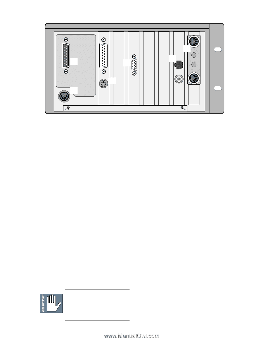
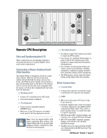
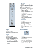
CONSOLE DATA PARALLEL 4 KEYBOARD 2 3 MOUSE 1 5 6 CONCEIVED, DESIGNED, AND MANUFACTURED BY MACKIE DESIGNS INC • WOODINVILLE • WA • USA • MADE IN USA • FABRIQUE AU USA • COPYRIGHT ©1997 • THE FOLLOWING ARE TRADEMARKS OR REGISTERED TRADEMARKS OF MACKIE DESIGN INC.: "MACKIE", "DIGITAL SYSTEMS", D8B AND THE "RUNNING MAN" FIGURE • Remote CPU Description Data and Synchronization I/O These connections are specifically pertinent to non-audio functions (or, in plain English, these aren't audio connections!). Connecting a Mouse, Keyboard and SVGA Monitor The Digital 8•Bus is designed to work as a standalone console. However, you'll increase your options and productivity by using a mouse, keyboard, and SVGA monitor. Simply connect them to the corresponding ports on the back of the Remote CPU for access to point-and-click commands with the mouse, as well as key commands and text entry from the keyboard. 1 The Mouse Port • Connect a PC-compatible mouse (PS/2 style). • A two-button mouse is sufficient. 2 The Keyboard • Connect any PC-compatible keyboard (QWERTY style). • Must have a 5-pin DIN connector. An adapter can be used for the 9-pin keyboard connector. Note: Turn the Digital 8•Bus OFF before connecting these devices. The Digital 8•Bus must boot up with these peripheral devices connected in order for them to work properly. 3 The SVGA Monitor • A hi-density 15-pin D-Sub connector is provided to connect an SVGA monitor. • Use at least a 17" multisync SVGA monitor capable of 1024 X 768 resolution and a 72Hz refresh rate. Larger monitors provide greater viewing pleasure. • Use of monitor provides graphic display and control of most console functions, including equalization, compression, gating, internal effects, automation editing, and file management. • The SVGA monitor can be connected without turning off the Digital 8•Bus (hot-plugable). Other Connections 4 Console Data • A 25-pin D-sub connector connects the console to the Remote CPU using the cable supplied. 5 MIDI • MIDI card in the remote CPU uses a 9-pin D-sub connector. • Install the supplied 9-pin to dual 5-pin adapter to facilitate connection to your MIDI network using standard MIDI cables. This could be a plastic housing adapter or a rattail 9-pin split to 5-pin I/O connection. • MIDI IN receives MTC, program changes, and controller, note, and poly aftertouch messages. • MIDI OUT sends MMC commands, program changes, and controller, note, and poly aftertouch messages. • The MIDI card can be replaced with the Serial•9 card, which provides both MIDI and Sony 9-Pin communication. D8B Manual • Chapter 2 • page 25
-
 1
1 -
2
-
3
-
4
-
5
-
6
-
7
-
8
-
9
-
10
-
11
-
12
-
13
-
14
-
15
-
16
-
17
-
18
-
19
-
20
-
21
-
22
-
23
-
24
-
25
-
 26
26 -
 27
27 -
 28
28 -
 29
29 -
 30
30 -
 31
31 -
 32
32 -
 33
33 -
 34
34 -
 35
35 -
 36
36 -
37
-
38
-
39
-
40
-
41
-
42
-
43
-
44
-
45
-
46
-
47
-
48
-
49
-
50
-
51
-
52
-
53
-
54
-
55
-
56
-
57
-
58
-
59
-
60
-
61
-
62
-
63
-
64
-
65
-
66
-
67
-
68
-
69
-
70
-
71
-
72
-
73
-
74
-
75
-
76
-
77
-
78
-
79
-
80
-
81
-
82
-
83
-
84
-
85
-
86
-
87
-
88
-
89
-
90
-
91
-
92
-
93
-
94
-
95
-
96
-
97
-
98
-
99
-
100
-
101
-
102
-
103
-
104
-
105
-
106
-
107
-
108
-
109
-
110
-
111
-
112
-
113
-
114
-
115
-
116
-
117
-
118
-
119
-
120
-
121
-
122
-
123
-
124
-
125
-
126
-
127
-
128
-
129
-
130
-
131
-
132
-
133
-
134
-
135
-
136
-
137
-
138
-
139
-
140
-
141
-
142
-
143
-
144
-
145
-
146
-
147
-
148
-
149
-
150
-
151
-
152
-
153
-
154
-
155
-
156
-
157
-
158
-
159
-
160
-
161
-
162
-
163
-
164
-
165
-
166
-
167
-
168
-
169
-
170
-
171
-
172
-
173
-
174
-
175
-
176
-
177
-
178
-
179
-
180
-
181
-
182
-
183
-
184
-
185
-
186
-
187
-
188
-
189
-
190
-
191
-
192
-
193
-
194
-
195
-
196
-
197
-
198
 |
 |