Mackie D8B Owners Manual - Page 92
THRESHOLD, ATTACK, RELEASE, RATIO, OUTPUT, Double-click the COMPRESSOR and GATE
 |
View all Mackie D8B manuals
Add to My Manuals
Save this manual to your list of manuals |
Page 92 highlights
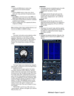
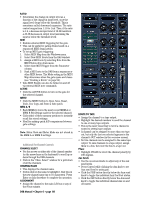
SOFT • This button turns on the compressor soft knee function. The knee of the compressor describes the point on the input-output graph where the threshold begins to reduce the output. • A hard-knee compressor means that, up until the moment the input signal crosses the threshold, no compression occurs; once the threshold is crossed, the full ratio of gain reduction is applied to the input signal (assuming the attack time has passed). When there is no signal applied, the Reduction meter indicates 0 dB of reduction, with the needle all the way to the right. As the signal level increases above the Threshold setting of the Compressor, the needle moves down, indicating the amount of compression being applied at any given moment in time, to a maximum of 20 dB of reduction. Additionally, there is a "signal present" indicator (the green LED) near the top of the meter, which simulates an analog signal present LED. It begins to light at -40 dB and becomes fully lit when the signal passes -20 dB. Note that the Reduction meter is triggered by the Compressor function only, and does not indicate the closing or opening of the gate. THRESHOLD • Determines the level at which the compressor begins to act on the incoming signal. It is calibrated in decibels, ranging from -60.0 dB to -1.0 dB. ATTACK • Determines how fast the compressor reacts once the threshold has been exceeded. It is calibrated in milliseconds, ranging from 0.1 ms to 2500 ms (2.5 seconds). RELEASE • Determines how fast the compressor turns off once the signal falls below the threshold. It is calibrated in milliseconds, ranging from10.0 ms to 2500 ms (2.5 seconds). RATIO • Determines the change in output level as a function of the change in input level, once the threshold has been exceeded. The Ratio control ranges from 1.0:1 to inf:1. Thus, if the ratio is 10:1, an increase in input level of 10 dB (assuming the input is above the threshold level), results in a 1 dB increase in output level. • When set to inf:1, the compressor acts as a peak limiter. After the initial attack time, the output does not get any higher than the threshold. OUTPUT • Determines the amount of make-up gain applied after the compressor. Use this control to compensate for the loss of gain caused by the action of the compressor. It is calibrated in decibels, ranging from unity (0.0 dB) to +20.0 dB. D8B Manual • Chapter 3 • page 86 • With the soft knee engaged, the gain reduction begins to occur before the input signal reaches the threshold. The amount of reduction gradually increases until the full ratio setting is reached slightly after the threshold is crossed. This can be seen as a curve around the knee point on the compressor graphic display. VIEW • This button opens a graphical view of the compressor and gate gain reduction curves (input signal level vs. output signal level). • Click and drag on the nodes in the windows to change the parameters of the compressor and gate. Tip: Double-click the COMPRESSOR and GATE buttons in the Fat Channel section on the console to open and close the expanded dynamics view. Double-click in the blue background of the expanded dynamics view to close the expanded view window.
-
 1
1 -
2
-
3
-
4
-
5
-
6
-
7
-
8
-
9
-
10
-
11
-
12
-
13
-
14
-
15
-
16
-
17
-
18
-
19
-
20
-
21
-
22
-
23
-
24
-
25
-
26
-
27
-
28
-
29
-
30
-
31
-
32
-
33
-
34
-
35
-
36
-
37
-
38
-
39
-
40
-
41
-
42
-
43
-
44
-
45
-
46
-
47
-
48
-
49
-
50
-
51
-
52
-
53
-
54
-
55
-
56
-
57
-
58
-
59
-
60
-
61
-
62
-
63
-
64
-
65
-
66
-
67
-
68
-
69
-
70
-
71
-
72
-
73
-
74
-
75
-
76
-
77
-
78
-
79
-
80
-
81
-
82
-
83
-
84
-
85
-
86
-
 87
87 -
 88
88 -
 89
89 -
 90
90 -
 91
91 -
 92
92 -
 93
93 -
 94
94 -
 95
95 -
 96
96 -
 97
97 -
98
-
99
-
100
-
101
-
102
-
103
-
104
-
105
-
106
-
107
-
108
-
109
-
110
-
111
-
112
-
113
-
114
-
115
-
116
-
117
-
118
-
119
-
120
-
121
-
122
-
123
-
124
-
125
-
126
-
127
-
128
-
129
-
130
-
131
-
132
-
133
-
134
-
135
-
136
-
137
-
138
-
139
-
140
-
141
-
142
-
143
-
144
-
145
-
146
-
147
-
148
-
149
-
150
-
151
-
152
-
153
-
154
-
155
-
156
-
157
-
158
-
159
-
160
-
161
-
162
-
163
-
164
-
165
-
166
-
167
-
168
-
169
-
170
-
171
-
172
-
173
-
174
-
175
-
176
-
177
-
178
-
179
-
180
-
181
-
182
-
183
-
184
-
185
-
186
-
187
-
188
-
189
-
190
-
191
-
192
-
193
-
194
-
195
-
196
-
197
-
198
 |
 |
