Mackie D8B Owners Manual - Page 16
Signal Routing Concept - support
 |
View all Mackie D8B manuals
Add to My Manuals
Save this manual to your list of manuals |
Page 16 highlights
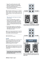
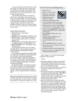
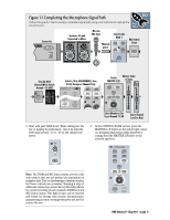
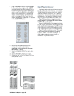
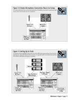
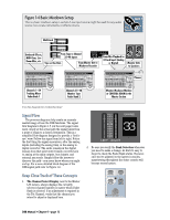
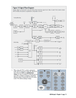
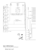
7. In the ASSIGNMENT section, verify that when L-R is selected (green light on) the ASSIGN button in Channel One lights up green. This is basic bus assignment procedure. Anything you want to come out the MASTER L-R bus must light up on the assign button of each desired channel. In similar fashion, any channel that needs to be assigned to Bus 1 must have the channel assign button lit when Bus 1 is selected in the ASSIGNMENT section. ASSIGNMENT ASSIGN BUS 1 ASSIGN BUS 3 ASSIGN BUS 5 ASSIGN BUS 7 ASSIGN L-R ASSIGN BUS 2 ASSIGN BUS 4 ASSIGN BUS 6 ASSIGN BUS 8 ASSIGN ROUTE TO TAPE 8. Be sure the SPEAKER button is lit that corresponds to your monitor system connection-that the yellow light shows on NEAR FIELD or MAIN. 9. Turn the SPEAKER LEVEL V-pot up to about 11:00. 10. Turn the MASTER L/R fader up to unity. 11. Slowly raise the level of the Channel One fader until you hear sound. Signal Routing Concept The Digital 8•Bus, with its multilayer technology, literally performs the work of at least four consoles. To help organize the various connections, visualize each bank as a new console. The "V" or "Multi-V" diagrams that follow provide a simple and accurate mental image of the signal flow and/or processing while you put the Digital 8•Bus through its paces. Figure 1-2 demonstrates a simple connection scheme utilizing a microphone that's routed though the D8B to the monitor system. Figure 1-3 demonstrates a tracking setup. Notice how the graphic representation of two separate fader banks supports the mental image of the D8B concept: sound source into the MIC/LINE bank, then routed to the multitrack, then back into the TAPE IN bank. Figure 1-4 adds a mixdown recorder. The beauty of this concept lies in its flexibility. Start at the beginning, middle, or end of the signal path-it doesn't matter. When the routing concept is understood, the process is simple. TRIM LINE TRIM 12 REC/RDY ASSIGN WRITE REC/RDY ASSIGN WRITE 10 10 20 20 30 30 40 40 50 50 60 60 ASSIGNMENT ASSIGN ASSIGN BUS 7 ASSIGN L-R ASSIGN BUS 2 BUS 8 ASSIGN ROUTE TO TAPE D8B Manual • Chapter 1 • page 10
-
 1
1 -
2
-
3
-
4
-
5
-
6
-
7
-
8
-
9
-
10
-
 11
11 -
 12
12 -
 13
13 -
 14
14 -
 15
15 -
 16
16 -
 17
17 -
 18
18 -
 19
19 -
 20
20 -
 21
21 -
22
-
23
-
24
-
25
-
26
-
27
-
28
-
29
-
30
-
31
-
32
-
33
-
34
-
35
-
36
-
37
-
38
-
39
-
40
-
41
-
42
-
43
-
44
-
45
-
46
-
47
-
48
-
49
-
50
-
51
-
52
-
53
-
54
-
55
-
56
-
57
-
58
-
59
-
60
-
61
-
62
-
63
-
64
-
65
-
66
-
67
-
68
-
69
-
70
-
71
-
72
-
73
-
74
-
75
-
76
-
77
-
78
-
79
-
80
-
81
-
82
-
83
-
84
-
85
-
86
-
87
-
88
-
89
-
90
-
91
-
92
-
93
-
94
-
95
-
96
-
97
-
98
-
99
-
100
-
101
-
102
-
103
-
104
-
105
-
106
-
107
-
108
-
109
-
110
-
111
-
112
-
113
-
114
-
115
-
116
-
117
-
118
-
119
-
120
-
121
-
122
-
123
-
124
-
125
-
126
-
127
-
128
-
129
-
130
-
131
-
132
-
133
-
134
-
135
-
136
-
137
-
138
-
139
-
140
-
141
-
142
-
143
-
144
-
145
-
146
-
147
-
148
-
149
-
150
-
151
-
152
-
153
-
154
-
155
-
156
-
157
-
158
-
159
-
160
-
161
-
162
-
163
-
164
-
165
-
166
-
167
-
168
-
169
-
170
-
171
-
172
-
173
-
174
-
175
-
176
-
177
-
178
-
179
-
180
-
181
-
182
-
183
-
184
-
185
-
186
-
187
-
188
-
189
-
190
-
191
-
192
-
193
-
194
-
195
-
196
-
197
-
198
 |
 |
