Mackie D8B Owners Manual - Page 134
Connecting the Digital 8•Bus to ADATs Using an External Sync Box, ADATs, Notes
 |
View all Mackie D8B manuals
Add to My Manuals
Save this manual to your list of manuals |
Page 134 highlights
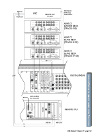
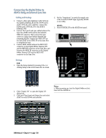
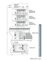
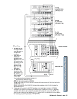
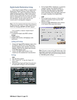
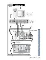
Connecting the Digital 8•Bus to ADATs Using an External Sync Box Cabling and Hookup 1. Connect a fiber optic (lightpipe) cable between the ADAT's DIGITAL IN and the DIO•8 card's ADAT OPTICAL OUT. Likewise, connect the DIO•8 cards' OPTICAL IN to the ADAT's DIGITAL OUT. 2. Connect the 9-pin D-sub sync cables between the Sync Box (SYNC OUT) and the first ADAT's SYNC IN connector. Then connect the sync cables in a daisy-chain fashion between the remaining ADATs. Connect the SYNC OUT on the last ADAT to the SYNC IN on the Sync Box to complete the loop. 3. Connect MIDI cables between the MIDI OUT connector on the Digital 8•Bus' Remote CPU and the MIDI IN connector on the Sync Box, and between the MIDI IN connector on the Digital 8•Bus' Remote CPU and the MIDI OUT connector on the Sync Box. Settings D8B 1. Open the Setup window by pressing Ctrl+1 or clicking Setup in the bottom menu bar on-screen. 4. Set the "Samplerate" to match the sample rate of the formatted ADAT tapes (typically 48 kHz or 44.1 kHz). ADATs 1. Select DIGITAL IN on the ADAT front panel. Modular Digital Multitrack CLOCK EXT 48K INPUT MON INPUT DIGITAL INPUT SELECT DIGITAL INPUT TRACK COPY INPUT MONITOR ALL INPUT AUTO INPUT 2. Click "Digital I/O" to open the Digital I/O dialog box. 3. Click each Tape Input and Output box and select ADAT for each DIO•8 card installed. Notes: • When powering up, turn the Digital 8•Bus on first, then turn the ADATs on. D8B Manual • Chapter 4 • page 128
-
 1
1 -
2
-
3
-
4
-
5
-
6
-
7
-
8
-
9
-
10
-
11
-
12
-
13
-
14
-
15
-
16
-
17
-
18
-
19
-
20
-
21
-
22
-
23
-
24
-
25
-
26
-
27
-
28
-
29
-
30
-
31
-
32
-
33
-
34
-
35
-
36
-
37
-
38
-
39
-
40
-
41
-
42
-
43
-
44
-
45
-
46
-
47
-
48
-
49
-
50
-
51
-
52
-
53
-
54
-
55
-
56
-
57
-
58
-
59
-
60
-
61
-
62
-
63
-
64
-
65
-
66
-
67
-
68
-
69
-
70
-
71
-
72
-
73
-
74
-
75
-
76
-
77
-
78
-
79
-
80
-
81
-
82
-
83
-
84
-
85
-
86
-
87
-
88
-
89
-
90
-
91
-
92
-
93
-
94
-
95
-
96
-
97
-
98
-
99
-
100
-
101
-
102
-
103
-
104
-
105
-
106
-
107
-
108
-
109
-
110
-
111
-
112
-
113
-
114
-
115
-
116
-
117
-
118
-
119
-
120
-
121
-
122
-
123
-
124
-
125
-
126
-
127
-
128
-
 129
129 -
 130
130 -
 131
131 -
 132
132 -
 133
133 -
 134
134 -
 135
135 -
 136
136 -
 137
137 -
 138
138 -
 139
139 -
140
-
141
-
142
-
143
-
144
-
145
-
146
-
147
-
148
-
149
-
150
-
151
-
152
-
153
-
154
-
155
-
156
-
157
-
158
-
159
-
160
-
161
-
162
-
163
-
164
-
165
-
166
-
167
-
168
-
169
-
170
-
171
-
172
-
173
-
174
-
175
-
176
-
177
-
178
-
179
-
180
-
181
-
182
-
183
-
184
-
185
-
186
-
187
-
188
-
189
-
190
-
191
-
192
-
193
-
194
-
195
-
196
-
197
-
198
 |
 |
