Mackie D8B Owners Manual - Page 15
Completing the Microphone Signal Path, Select L/R in ASSIGNMENT, then - digital mixer
 |
View all Mackie D8B manuals
Add to My Manuals
Save this manual to your list of manuals |
Page 15 highlights
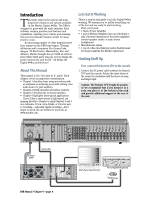
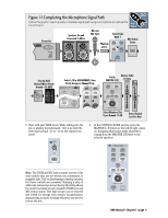
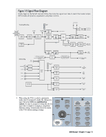
Figure 1-1 Completing the Microphone Signal Path Follow this graphic map to quickly complete a signal path using a microphone to capture the sound source.. FAST TRACK Power On Speakers On and Connected to Mixer Mic into Mic Input Select Fader Bank 1 Phantom power MASTERS 1-24 SHIFT 25-48 MIC/LINE (TRACK) TAPE IN (MONITOR) 49-72 Mic Button Down MIC EFFECTS BANK SELECT Trim Up Until Channel Meter Reads Around -15 dBFS TRIM LINE MIC 0 60 -20dB +40dB 1 1 OL 2 4 7 10 15 20 25 30 40 50 60 25 Select L/R in ASSIGNMENT, then Verify Assign on Channel Strip ASSIGNMENT REC/RDY REC/RDY ASSIGN ASSIGN BUS 7 ASSIGN L-R ASSIGN BUS 2 BUS 8 ASSIGN ROUTE TO TAPE ASSIGN WRITE ASSIGN WRITE Verify MASTER L/R 2 TRACK C MASTER L-R MONO OR NEAR FIELD SPEAKERS MAIN SPEAKER LEVEL Master Fader at Unity MASTER L/R dB 10 5 U 5 10 20 30 40 50 60 GROUP 1 FX 1 1 25 dB 10 5 U 5 10 20 30 40 50 60 Select Monitors/Set V-pot Around 11:00 Raise Channel Level to Hear 5. Start with gain TRIM down. While talking into the mic or playing the instrument, turn it up until the level stays around -15 to -10 on the channel one meter. TRIM LINE MIC 0 60 -20dB +40dB 1 MIC Note: The TRIM and MIC button status are two of the only controls that are not written into automation or snapshot data. That's a disadvantage of analog circuitry, but these controls are necessary. Running a strip of white safe-release tape across the top label strip allows for careful recording of each channel's TRIM level and MIC button status. This kind of tape can be removed and folded for storage with session documentation, guaranteeing accurate settings whenever you need to restore the mix. 6. In the CONTROL ROOM section, press the MASTER L-R button so the yellow light comes on. Assigning this button sends whatever is coming from the MASTER L/R fader to the selected speakers. CONTROL ROOM 2 TRACK A DIGITAL IN 1 2 TRACK B DIGITAL IN 2 2 TRACK C MASTER L-R MONO OR NEAR FIELD MAIN SPEAKERS SPEAKER LEVEL DIM TALKBACK D8B Manual • Chapter 1 • page 9
-
 1
1 -
2
-
3
-
4
-
5
-
6
-
7
-
8
-
9
-
 10
10 -
 11
11 -
 12
12 -
 13
13 -
 14
14 -
 15
15 -
 16
16 -
 17
17 -
 18
18 -
 19
19 -
 20
20 -
21
-
22
-
23
-
24
-
25
-
26
-
27
-
28
-
29
-
30
-
31
-
32
-
33
-
34
-
35
-
36
-
37
-
38
-
39
-
40
-
41
-
42
-
43
-
44
-
45
-
46
-
47
-
48
-
49
-
50
-
51
-
52
-
53
-
54
-
55
-
56
-
57
-
58
-
59
-
60
-
61
-
62
-
63
-
64
-
65
-
66
-
67
-
68
-
69
-
70
-
71
-
72
-
73
-
74
-
75
-
76
-
77
-
78
-
79
-
80
-
81
-
82
-
83
-
84
-
85
-
86
-
87
-
88
-
89
-
90
-
91
-
92
-
93
-
94
-
95
-
96
-
97
-
98
-
99
-
100
-
101
-
102
-
103
-
104
-
105
-
106
-
107
-
108
-
109
-
110
-
111
-
112
-
113
-
114
-
115
-
116
-
117
-
118
-
119
-
120
-
121
-
122
-
123
-
124
-
125
-
126
-
127
-
128
-
129
-
130
-
131
-
132
-
133
-
134
-
135
-
136
-
137
-
138
-
139
-
140
-
141
-
142
-
143
-
144
-
145
-
146
-
147
-
148
-
149
-
150
-
151
-
152
-
153
-
154
-
155
-
156
-
157
-
158
-
159
-
160
-
161
-
162
-
163
-
164
-
165
-
166
-
167
-
168
-
169
-
170
-
171
-
172
-
173
-
174
-
175
-
176
-
177
-
178
-
179
-
180
-
181
-
182
-
183
-
184
-
185
-
186
-
187
-
188
-
189
-
190
-
191
-
192
-
193
-
194
-
195
-
196
-
197
-
198
 |
 |
