Sony PDWHD1500 User Manual (PDW-HD1500 / F1600 Operation Manual for Firmware V - Page 17
Names and Functions of Parts, Front Panel
 |
View all Sony PDWHD1500 manuals
Add to My Manuals
Save this manual to your list of manuals |
Page 17 highlights
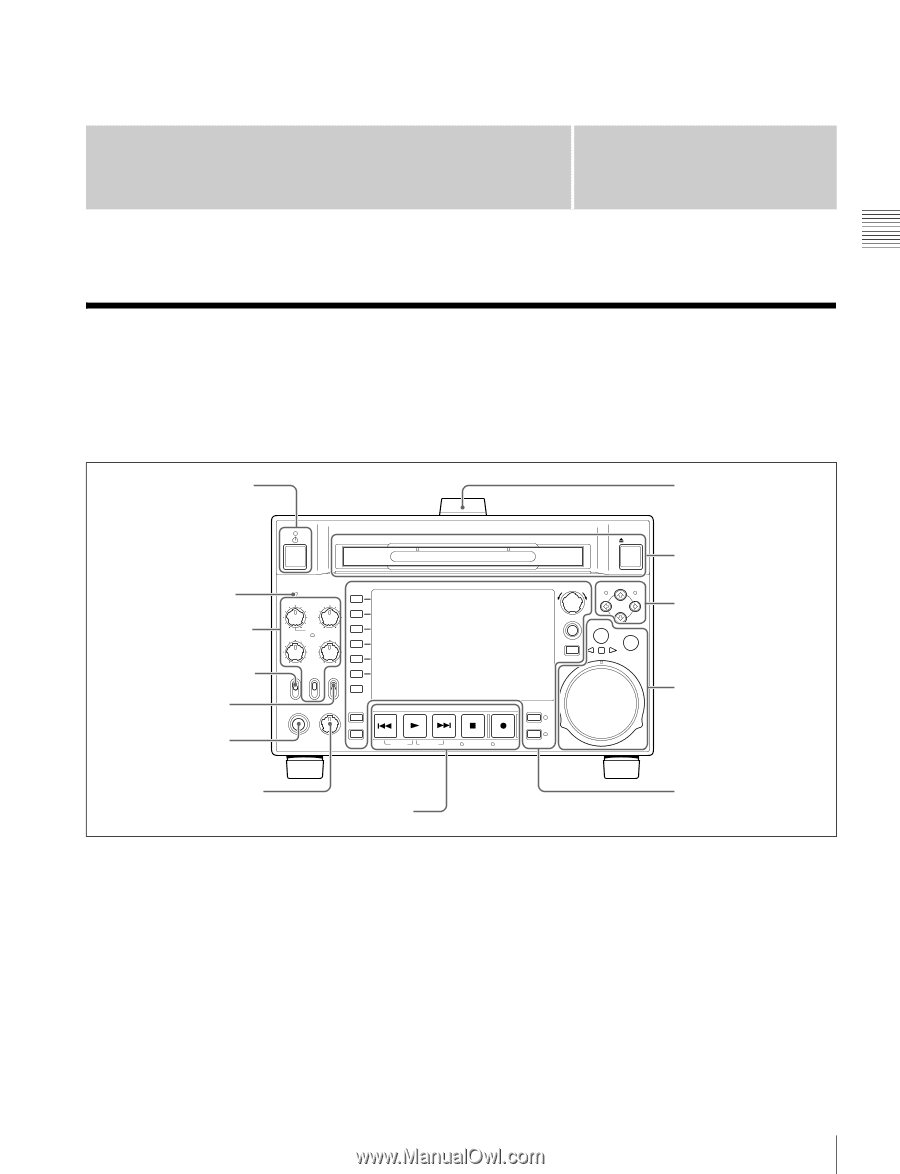
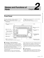
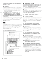
Names and Functions of Parts 2 Chapter Chapter 2 Names and Functions of Parts Front Panel The names and symbols of buttons and knobs on the front panel are color coded according to function. White: Function when the button or knob is operated independently. Orange: Function when the button is operated with the SHIFT button held down. Blue: Function related to thumbnail operations. 1 On/standby button and indicator Handle EJECT 2 ACCESS indicator 1 Audio level adjustment section (see page 18) 3 Remote control switch 4 KEY INHI switch 5 PHONES jack ACCESS CH-1 CH-3 PUSH SET(S.SEL) MARK1 IN OUT ALL CH CH-2 CH-4 CHAPTER NET LOCAL REMOTE VARIABLE KEY INHI REC PRE- ON SET OFF PB EXPAND PAGE HOME PHONES LEVEL DISPLAY PREV PLAY NEXT STOP REC THUMBNAIL MENU RESET SHTL/JOG MARK2 VAR/JOG RETURN SHIFT SUB CLIP TOP F REV F FWD END STANDBY REC INHI DISC MENU 7 Disc slot and EJECT button 2 Arrow buttons (see page 18) 3 Shuttle/jog/variable control section (see page 19) 6 LEVEL adjustment knob 5 Recording and playback control section (see page 21) 4 Display/menu control section (see page 20) a On/standby (1) button and indicator When the POWER switch on the rear panel is in the @ position, and when DC power is connected to the DC IN 12V connector on the rear panel, this switches the unit between the operating state (the indicator is lit green) and the standby state (the indicator is lit red). When the indicator is lit red, pressing the button switches this unit to the operating state, and the indicator lights continuously green. When the indicator is lit green, pressing the button switches the unit to the standby state, and the indicator lights continuously red. If a disc is loaded in the unit, the indicator flashes before changing to continuously lit red. When using this unit, normally leave the rear panel POWER switch in the @ (on) position, and use this button to switch the unit between the operating state and standby state. b ACCESS indicator This lights when the disc is accessed and when a file is opened by a FAM or FTP connection (see page 104). If the on/standby button is pressed while this indicator is lit, 17 Front Panel
-
 1
1 -
2
-
3
-
4
-
5
-
6
-
7
-
8
-
9
-
10
-
11
-
 12
12 -
 13
13 -
 14
14 -
 15
15 -
 16
16 -
 17
17 -
 18
18 -
 19
19 -
 20
20 -
 21
21 -
 22
22 -
23
-
24
-
25
-
26
-
27
-
28
-
29
-
30
-
31
-
32
-
33
-
34
-
35
-
36
-
37
-
38
-
39
-
40
-
41
-
42
-
43
-
44
-
45
-
46
-
47
-
48
-
49
-
50
-
51
-
52
-
53
-
54
-
55
-
56
-
57
-
58
-
59
-
60
-
61
-
62
-
63
-
64
-
65
-
66
-
67
-
68
-
69
-
70
-
71
-
72
-
73
-
74
-
75
-
76
-
77
-
78
-
79
-
80
-
81
-
82
-
83
-
84
-
85
-
86
-
87
-
88
-
89
-
90
-
91
-
92
-
93
-
94
-
95
-
96
-
97
-
98
-
99
-
100
-
101
-
102
-
103
-
104
-
105
-
106
-
107
-
108
-
109
-
110
-
111
-
112
-
113
-
114
-
115
-
116
-
117
-
118
-
119
-
120
-
121
-
122
-
123
-
124
-
125
-
126
-
127
-
128
-
129
-
130
-
131
-
132
-
133
-
134
-
135
-
136
-
137
-
138
-
139
-
140
-
141
-
142
-
143
-
144
-
145
-
146
-
147
-
148
-
149
-
150
-
151
-
152
-
153
-
154
-
155
-
156
-
157
-
158
-
159
-
160
-
161
-
162
-
163
-
164
-
165
-
166
-
167
-
168
-
169
-
170
-
171
-
172
-
173
-
174
-
175
-
176
-
177
-
178
-
179
-
180
-
181
-
182
-
183
-
184
-
185
-
186
-
187
-
188
 |
 |