Sony PDWHD1500 User Manual (PDW-HD1500 / F1600 Operation Manual for Firmware V - Page 41
Using the editing functions of the recorder (controlling through REMOTE(9P) connector) - pdw hd1500 maintenance manual
 |
View all Sony PDWHD1500 manuals
Add to My Manuals
Save this manual to your list of manuals |
Page 41 highlights
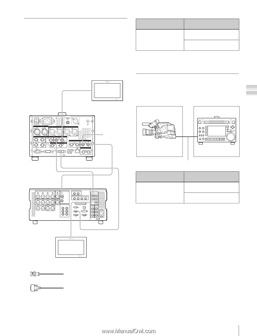
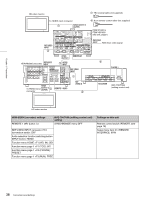
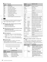
Chapter 3 Preparations Using the editing functions of the recorder (controlling through REMOTE(9P) connector) The following figure shows a cut editing system comprising this unit as a player, and an HDW-M2000/ M2000P unit as a recorder. In this example, video and audio signals are connected by HDSDI, and control signals are transferred via the REMOTE(9P) connector. HD video monitor To HDSDI input connector 1 HDSDI OUTPUT2 (SUPER) PDW-F1600 or PDW-HD1500 (this unit, player) POWER AC IN REMOTE DC IN 12V= ANALOG AUDIO INPUT 1 2 ANALOG AUDIO OUTPUT 1 2 AUDIO MONITOR R L DIGITAL AUDIO (AES/EBU) SD/HDSDI INPUT IN 1/2 3/4 1 HDSDI OUTPUT 2 (SUPER) OUT 1/2 S400 3/4 VIDEO CONTROL SDSDI OUTPUT 1 2 (SUPER) COMPOSITE OUTPUT 1 2 (SUPER) REMOTE(9P) MAINTENANCE REF.VIDEO INPUT IN TIME CODE IN OUT HDSDI OUTPUT1 REMOTE(9P) REF.VIDEO INPUT Reference 1 video signal REF.VIDEO INPUT 1 HDW-M2000 (recorder) REF VIDEO INPUT 1 HDSDI INPUT 75Ω 2 HDW-M2000 (recorder) setting REMOTE 1 (9P) button: Unlit Settings on this unit Remote control switch: REMOTE (see page 18) Setup menu item 214 REMOTE INTERFACE: 9PIN For details of HDW-M2000/M2000P settings, refer to the HDW-M2000/M2000P Operation Manual. Connections for pool coverage The following figure shows an example of connections for pool coverage, with the PDW-700 Professional Disc Camcorder connected. PDW-700 PDW-F1600 or PDWHD1500 (this unit) To SDI OUT 1 connector To SD/HDSDI INPUT connector 75Ω coaxial cable (not supplied) PDW-700 (camcorder) setting Settings on this unit HDSDI REMOTE I/F on Remote control switch: page CAM CONFIG 1 of REMOTE (see page 18) the MAINTENANCE menu: other than OFF Setup menu item 214 REMOTE INTERFACE: SDI To HDSDI input connector HDSDI OUTPUT 3 (SUPER) 1 REMOTE 1-OUT(9P) HD video monitor 1: 75Ω coaxial cable (not supplied) 2: 9-pin remote control cable (not supplied) 41 Connections and Settings
-
 1
1 -
2
-
3
-
4
-
5
-
6
-
7
-
8
-
9
-
10
-
11
-
12
-
13
-
14
-
15
-
16
-
17
-
18
-
19
-
20
-
21
-
22
-
23
-
24
-
25
-
26
-
27
-
28
-
29
-
30
-
31
-
32
-
33
-
34
-
35
-
 36
36 -
 37
37 -
 38
38 -
 39
39 -
 40
40 -
 41
41 -
 42
42 -
 43
43 -
 44
44 -
 45
45 -
 46
46 -
47
-
48
-
49
-
50
-
51
-
52
-
53
-
54
-
55
-
56
-
57
-
58
-
59
-
60
-
61
-
62
-
63
-
64
-
65
-
66
-
67
-
68
-
69
-
70
-
71
-
72
-
73
-
74
-
75
-
76
-
77
-
78
-
79
-
80
-
81
-
82
-
83
-
84
-
85
-
86
-
87
-
88
-
89
-
90
-
91
-
92
-
93
-
94
-
95
-
96
-
97
-
98
-
99
-
100
-
101
-
102
-
103
-
104
-
105
-
106
-
107
-
108
-
109
-
110
-
111
-
112
-
113
-
114
-
115
-
116
-
117
-
118
-
119
-
120
-
121
-
122
-
123
-
124
-
125
-
126
-
127
-
128
-
129
-
130
-
131
-
132
-
133
-
134
-
135
-
136
-
137
-
138
-
139
-
140
-
141
-
142
-
143
-
144
-
145
-
146
-
147
-
148
-
149
-
150
-
151
-
152
-
153
-
154
-
155
-
156
-
157
-
158
-
159
-
160
-
161
-
162
-
163
-
164
-
165
-
166
-
167
-
168
-
169
-
170
-
171
-
172
-
173
-
174
-
175
-
176
-
177
-
178
-
179
-
180
-
181
-
182
-
183
-
184
-
185
-
186
-
187
-
188
 |
 |