Sony PDWHD1500 User Manual (PDW-HD1500 / F1600 Operation Manual for Firmware V - Page 51
P5 Tc P6 Ref P7 Other Setting, Preset, Free Run, 24f Tc, 30f Tc, Input, Sub-item
 |
View all Sony PDWHD1500 manuals
Add to My Manuals
Save this manual to your list of manuals |
Page 51 highlights
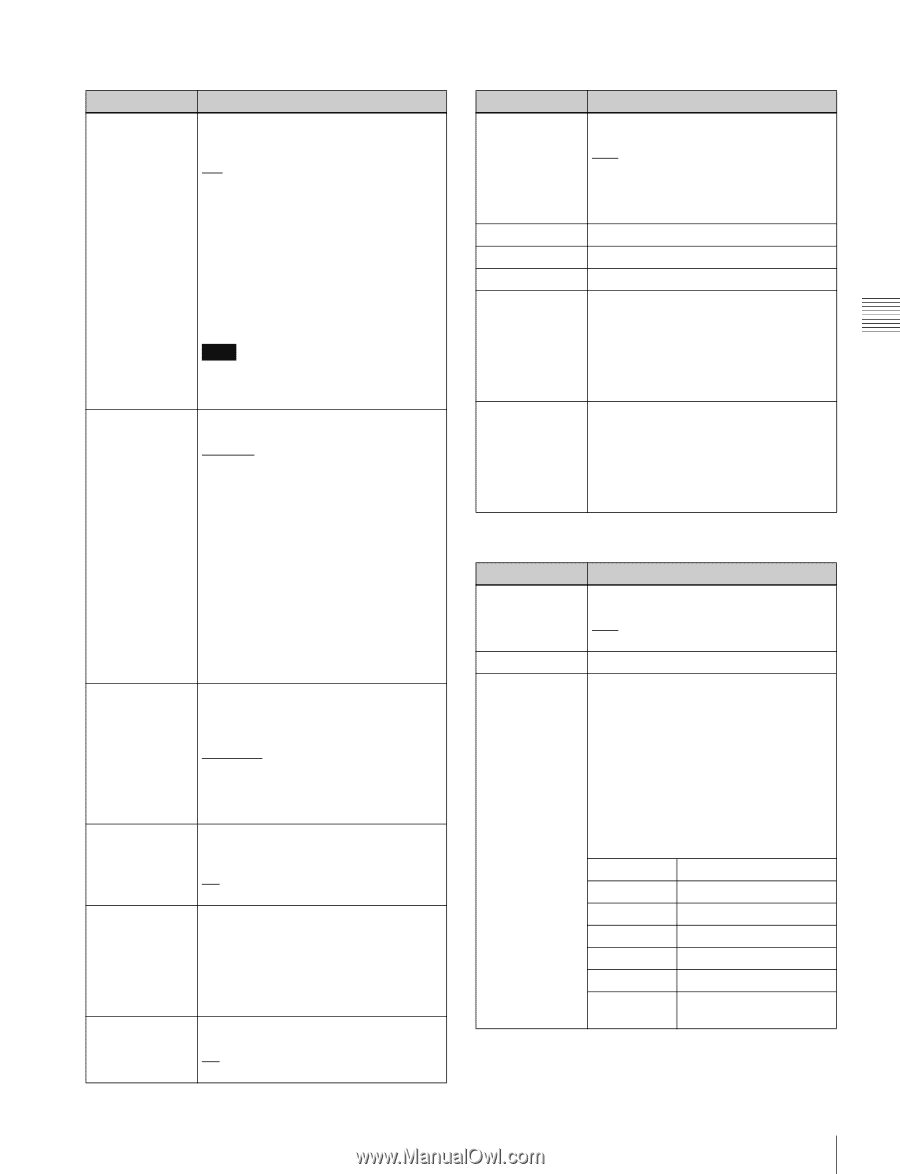
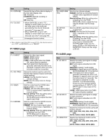
Chapter 3 Preparations P5 TC page Item F1: TCG F2: PRST/RGN F3: RUN MODE F4: DF/NDF F5: PDPSET F6: TCR Setting Selects the timecode signal to which the internal timecode generator synchronizes. INT: Follow the initial value set from the control panel or remotely from the device connected to the REMOTE(9P) connector, or synchronize to timecode played back from the disc. EXT: Synchronize to external timecode input to the TIME CODE IN connector. SDI: Synchronize to timecode embedded into HDSDI signal input to SD/HDSDI INPUT connector. Note If you select "EXT" or "SDI" while i.LINK TS signals are being input, synchronizes to the timecode data in the TS signals. Selects the following for the internal timecode generator. PRESET: Presets an initial value for the timecode generated by the internal timecode generator, as specified from the control panel or remotely from the device connected to the REMOTE(9P) connector. This is valid when "INT" is selected with the F1: TCG item on this page. The operation is the same as "TC" when anything else is selected. TC: Generate timecode synchronized to timecode read by the internal timecode reader. VITC: Generate timecode synchronized to VITC read by the internal timecode reader. Selects the timecode run mode. FREE RUN: Timecode advances as long as the unit is powered on, regardless of the unit's operating state. REC RUN: Timecode advances only during recording. When you select this item, also set F1: TCG on this page to "INT" and set F2: PRST/ RGN to "PRESET". Selects the drop-frame mode for the internal timecode generator and the counter in 59.94i/59.94P/29.97P mode. DF: Drop-frame mode NDF: Non-drop-frame mode When the system frequency is set to 1080/59.94i, 1080/29.97P, or 720/ 59.94P, presets the timecode of the A frame of the pulldown sequence. 24F TC: Reference timecode for A frame 30F TC: Timecode after pulldown conversion from 24-frame timecode Selects the type of timecode to display in the time data display area. TC: Display TC. VITC: Display VITC. P6 REF page Item F1: OUT REF F2: F3: F4: F5: SYNC F6: FINE Setting Selects the reference signal for the output signals of this unit. REF: Use the signal input to the REF.VIDEO INPUT connector as the output reference signal. INPUT: Use the input video signal as the output reference signal. (Unassigned function button) (Unassigned function button) (Unassigned function button) Sets the sync phase of HD output signals. While the setting value is flashing, turn the PUSH SET(S.SEL) knob to adjust the sync phase of output signals with respect to the input reference signal, over the range ±15 µs. (The display shows -128 to +127.) Makes fine adjustment to the sync phase of HD output signals. While the setting value is flashing, turn the PUSH SET(S.SEL) knob to adjust the sync phase of output signals with respect to the input reference signal, over the range ±200 ns. (The display shows 0 to 1023.) P7 OTHER page Item F1: CONV IMP F2: ERR LOG F3: CLIP FLG Setting Selects whether to display convert status on the display during convert operations. OFF: Do not display. ON: Display. Displays an error log screen. Sets a clip flag for the clip being recorded or played back using the function button. If a clip flag is already set for the clip, "Marked" is displayed in the function menu item corresponding to one of the F1 to F3 buttons depending on the type of flag that has been set. A clip flag can also be set or deleted using the GUI screen. See page 82 for details. Sub-Item F1: OK Set an OK flag. F2: NG Set an NG flag. F3: KEEP Set a KEEP flag. F4: - F5: DELETE Delete the clip flag. F6: EXIT Exit the clip flag submenu. 51 Basic Operations of the Function Menu
-
 1
1 -
2
-
3
-
4
-
5
-
6
-
7
-
8
-
9
-
10
-
11
-
12
-
13
-
14
-
15
-
16
-
17
-
18
-
19
-
20
-
21
-
22
-
23
-
24
-
25
-
26
-
27
-
28
-
29
-
30
-
31
-
32
-
33
-
34
-
35
-
36
-
37
-
38
-
39
-
40
-
41
-
42
-
43
-
44
-
45
-
 46
46 -
 47
47 -
 48
48 -
 49
49 -
 50
50 -
 51
51 -
 52
52 -
 53
53 -
 54
54 -
 55
55 -
 56
56 -
57
-
58
-
59
-
60
-
61
-
62
-
63
-
64
-
65
-
66
-
67
-
68
-
69
-
70
-
71
-
72
-
73
-
74
-
75
-
76
-
77
-
78
-
79
-
80
-
81
-
82
-
83
-
84
-
85
-
86
-
87
-
88
-
89
-
90
-
91
-
92
-
93
-
94
-
95
-
96
-
97
-
98
-
99
-
100
-
101
-
102
-
103
-
104
-
105
-
106
-
107
-
108
-
109
-
110
-
111
-
112
-
113
-
114
-
115
-
116
-
117
-
118
-
119
-
120
-
121
-
122
-
123
-
124
-
125
-
126
-
127
-
128
-
129
-
130
-
131
-
132
-
133
-
134
-
135
-
136
-
137
-
138
-
139
-
140
-
141
-
142
-
143
-
144
-
145
-
146
-
147
-
148
-
149
-
150
-
151
-
152
-
153
-
154
-
155
-
156
-
157
-
158
-
159
-
160
-
161
-
162
-
163
-
164
-
165
-
166
-
167
-
168
-
169
-
170
-
171
-
172
-
173
-
174
-
175
-
176
-
177
-
178
-
179
-
180
-
181
-
182
-
183
-
184
-
185
-
186
-
187
-
188
 |
 |