Sony PDWHD1500 User Manual (PDW-HD1500 / F1600 Operation Manual for Firmware V - Page 23
Display window, Basic operation display
 |
View all Sony PDWHD1500 manuals
Add to My Manuals
Save this manual to your list of manuals |
Page 23 highlights
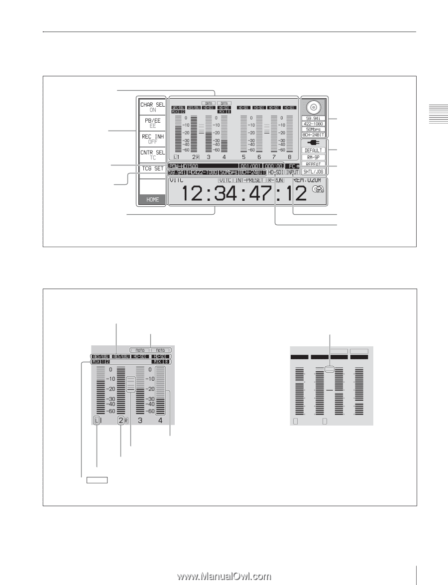
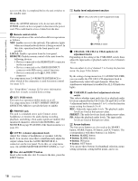
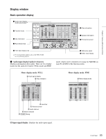
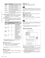
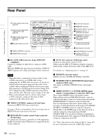
Chapter 2 Names and Functions of Parts Display window Basic operation display 1 Audio input display/ Audio level meters a) 2 Function menu 3 Clip information 4 Recording format 6 Disc information 7 System information 8 Format conversion 5 Time data display area a) The mixing display appears only on the PDW-F1600 (see the following figure). a Audio input display/Audio level meters Displays information about audio. There are two display modes for the audio level meter: FULL mode and FINE 9 Reference signal q; Video input display mode, which can be switched over using AU METER on page P4 AUDIO of the function menu. Meter display mode: FULL A Input signal display B Data indication G Level bar F Reference level E Audio channel D Monitor channel C F1600 Mixing Meter display mode: FINE H Meter display mode DATA DATA AES/EBU AES/EBU HD-SDI HD-SDI FINE 2 2 1 1 0 0 -1 -1 -2 -2 L1 2 R 3 4 A Input signal display: Displays the audio input signal. 23 Front Panel
-
 1
1 -
2
-
3
-
4
-
5
-
6
-
7
-
8
-
9
-
10
-
11
-
12
-
13
-
14
-
15
-
16
-
17
-
 18
18 -
 19
19 -
 20
20 -
 21
21 -
 22
22 -
 23
23 -
 24
24 -
 25
25 -
 26
26 -
 27
27 -
 28
28 -
29
-
30
-
31
-
32
-
33
-
34
-
35
-
36
-
37
-
38
-
39
-
40
-
41
-
42
-
43
-
44
-
45
-
46
-
47
-
48
-
49
-
50
-
51
-
52
-
53
-
54
-
55
-
56
-
57
-
58
-
59
-
60
-
61
-
62
-
63
-
64
-
65
-
66
-
67
-
68
-
69
-
70
-
71
-
72
-
73
-
74
-
75
-
76
-
77
-
78
-
79
-
80
-
81
-
82
-
83
-
84
-
85
-
86
-
87
-
88
-
89
-
90
-
91
-
92
-
93
-
94
-
95
-
96
-
97
-
98
-
99
-
100
-
101
-
102
-
103
-
104
-
105
-
106
-
107
-
108
-
109
-
110
-
111
-
112
-
113
-
114
-
115
-
116
-
117
-
118
-
119
-
120
-
121
-
122
-
123
-
124
-
125
-
126
-
127
-
128
-
129
-
130
-
131
-
132
-
133
-
134
-
135
-
136
-
137
-
138
-
139
-
140
-
141
-
142
-
143
-
144
-
145
-
146
-
147
-
148
-
149
-
150
-
151
-
152
-
153
-
154
-
155
-
156
-
157
-
158
-
159
-
160
-
161
-
162
-
163
-
164
-
165
-
166
-
167
-
168
-
169
-
170
-
171
-
172
-
173
-
174
-
175
-
176
-
177
-
178
-
179
-
180
-
181
-
182
-
183
-
184
-
185
-
186
-
187
-
188
 |
 |