Epson LQ-1000 User Manual - Page 126
Appendix F-the Parallel And Serial Interfaces, Appendix F
 |
View all Epson LQ-1000 manuals
Add to My Manuals
Save this manual to your list of manuals |
Page 126 highlights
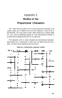
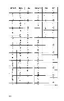
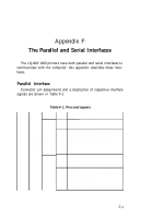
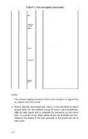
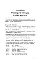
Appendix F The Parallel and Serial Interfaces The LQ-800/1000 printers have both parallel and serial interfaces to communicate with the computer; this appendix describes these interfaces. Parallel Interface Connector pin assignments and a description of respective interface signals are shown in Table F-1. Table F-1. Pins and signals Signal Return Pin Pin 1 19 2 20 3 21 4 22 5 23 6 24 7 25 8 26 9 27 10 28 11 29 DirecSignal tion STROBE IN DATA 1 IN DATA 2 IN DATA 3 DATA 4 IN DATA 5 IN DATA 6 DATA 7 IN DATA 8 IN ACKNLG OUT BUSY OUT Description STROBE pulse to read data in Pulse width must be more than 0.5 microseconds at the receiving terminal. These signals represent information of the 1st to 8th bits of parallel data, respectively Each signal is at HIGH level when data is logical 1 and LOW when it is logical 0. Approximately 12-microsecond pulse. LOW indicates that data has been received and that the printer is ready to accept more data. A HIGH signal indicates that the printer cannot receive data. The signal goes HIGH in the following cases: 1) During data entry (ea.char.time) 2) During printing 3) When Off-Line 4) During printer-error state F-1
-
 1
1 -
2
-
3
-
4
-
5
-
6
-
7
-
8
-
9
-
10
-
11
-
12
-
13
-
14
-
15
-
16
-
17
-
18
-
19
-
20
-
21
-
22
-
23
-
24
-
25
-
26
-
27
-
28
-
29
-
30
-
31
-
32
-
33
-
34
-
35
-
36
-
37
-
38
-
39
-
40
-
41
-
42
-
43
-
44
-
45
-
46
-
47
-
48
-
49
-
50
-
51
-
52
-
53
-
54
-
55
-
56
-
57
-
58
-
59
-
60
-
61
-
62
-
63
-
64
-
65
-
66
-
67
-
68
-
69
-
70
-
71
-
72
-
73
-
74
-
75
-
76
-
77
-
78
-
79
-
80
-
81
-
82
-
83
-
84
-
85
-
86
-
87
-
88
-
89
-
90
-
91
-
92
-
93
-
94
-
95
-
96
-
97
-
98
-
99
-
100
-
101
-
102
-
103
-
104
-
105
-
106
-
107
-
108
-
109
-
110
-
111
-
112
-
113
-
114
-
115
-
116
-
117
-
118
-
119
-
120
-
 121
121 -
 122
122 -
 123
123 -
 124
124 -
 125
125 -
 126
126 -
 127
127 -
 128
128 -
 129
129 -
 130
130 -
 131
131 -
132
-
133
-
134
-
135
-
136
-
137
-
138
-
139
-
140
-
141
-
142
-
143
-
144
-
145
-
146
-
147
-
148
-
149
-
150
-
151
-
152
-
153
-
154
-
155
-
156
-
157
-
158
-
159
-
160
-
161
-
162
-
163
-
164
-
165
-
166
-
167
-
168
-
169
-
170
-
171
-
172
-
173
-
174
-
175
-
176
-
177
-
178
-
179
-
180
-
181
-
182
-
183
-
184
-
185
 |
 |