Epson LQ-1000 User Manual - Page 127
Table F-1. Pins and signals continued, ground level. For the interface wiring
 |
View all Epson LQ-1000 manuals
Add to My Manuals
Save this manual to your list of manuals |
Page 127 highlights
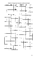
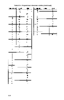
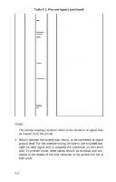
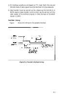
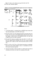
Table F-1. Pins and signals (continued) Signal Return Pin Pin Signal 12 30 PE 13 - SLCT Direction OUT OUT 14 - AUTO IN FEED XT 15 16 17 18 19-30 31 - - - - GND - - CHASSIS - GND - NC - - GND - 16 INIT IN 32 - ERROR OUT 33 - GND - 34 - - - 35 - - OUT 3 6 - SLCT- IN IN Description A HIGH signal indicates that the printer IS out of paper. Pulled up to + 5 volts through 3.3k ohm resistance. When this signal is LOW, the paper is automatically fed 1 line after printing. (The signal level can be fixed to this by setting DIP switch 2-8 to ON.) Unused. Ground for twisted-pair grounding. Printer's chassis ground, which is isolated from the logic ground. Unused Grounds for twisted-pair grounding. When this level becomes LOW, the printer controller is reset to its power-up state and the print buffer is cleared. This level is usually HIGH, its pulse width must be more than 50 microseconds at the receiving terminal. This level becomes LOW when the printer is in: 1) Paper-end state. 2) Off-Line. 3) Error state. Same as for Pins 19-30. Unused. Pulled up to + 5V through 3.3k ohm resistance. The DC1/DC3 code is valid only when this signal is HIGH. (Internal fixing can be carried out with DIP switch 2-7. The level of this signal is factory-set to LOW.) Notes: 1. The column heading Direction refers to the direction of signal flow as viewed from the printer. 2. Return denotes the twisted-pair return, to be connected at signal ground level. For the interface wiring, be sure to use a twisted-pair cable for each signal and to complete the connection on the return side. To prevent noise, these cables should be shielded and connected to the chassis of the host computer or the printer but not at both ends. F-2
-
 1
1 -
2
-
3
-
4
-
5
-
6
-
7
-
8
-
9
-
10
-
11
-
12
-
13
-
14
-
15
-
16
-
17
-
18
-
19
-
20
-
21
-
22
-
23
-
24
-
25
-
26
-
27
-
28
-
29
-
30
-
31
-
32
-
33
-
34
-
35
-
36
-
37
-
38
-
39
-
40
-
41
-
42
-
43
-
44
-
45
-
46
-
47
-
48
-
49
-
50
-
51
-
52
-
53
-
54
-
55
-
56
-
57
-
58
-
59
-
60
-
61
-
62
-
63
-
64
-
65
-
66
-
67
-
68
-
69
-
70
-
71
-
72
-
73
-
74
-
75
-
76
-
77
-
78
-
79
-
80
-
81
-
82
-
83
-
84
-
85
-
86
-
87
-
88
-
89
-
90
-
91
-
92
-
93
-
94
-
95
-
96
-
97
-
98
-
99
-
100
-
101
-
102
-
103
-
104
-
105
-
106
-
107
-
108
-
109
-
110
-
111
-
112
-
113
-
114
-
115
-
116
-
117
-
118
-
119
-
120
-
121
-
 122
122 -
 123
123 -
 124
124 -
 125
125 -
 126
126 -
 127
127 -
 128
128 -
 129
129 -
 130
130 -
 131
131 -
 132
132 -
133
-
134
-
135
-
136
-
137
-
138
-
139
-
140
-
141
-
142
-
143
-
144
-
145
-
146
-
147
-
148
-
149
-
150
-
151
-
152
-
153
-
154
-
155
-
156
-
157
-
158
-
159
-
160
-
161
-
162
-
163
-
164
-
165
-
166
-
167
-
168
-
169
-
170
-
171
-
172
-
173
-
174
-
175
-
176
-
177
-
178
-
179
-
180
-
181
-
182
-
183
-
184
-
185
 |
 |