Epson LQ-1000 User Manual - Page 130
Serial Interface, Odd, Even, or Non-Parity see Table A-4
 |
View all Epson LQ-1000 manuals
Add to My Manuals
Save this manual to your list of manuals |
Page 130 highlights
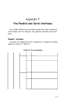
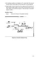
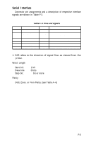
Serial Interface Connector pin assignments and a description of respective interface signals are shown in Table F-3. Table F-3. Pins and signals Pin No. 1 2 Signal name Not used REV (Reverse channel) 3 RXD 4 Not used 5 Signal GND 6 Chassis GND Dir Functional Description - Reserved. OUT Indicates printer is ready to receive data or not. MARK level indicates printer is not ready to receive data. I N Receives data (RS-232C level) - Reserved. - Signal (Logic) ground level. - Printer chassis ground. 1. DIR refers to the direction of signal flow as viewed from the printer. Word Length Start bit: Data bits: Stop bit: 1 bit 8 bits 1 bit or more Parity Odd, Even, or Non-Parity (see Table A-4) F-5
-
 1
1 -
2
-
3
-
4
-
5
-
6
-
7
-
8
-
9
-
10
-
11
-
12
-
13
-
14
-
15
-
16
-
17
-
18
-
19
-
20
-
21
-
22
-
23
-
24
-
25
-
26
-
27
-
28
-
29
-
30
-
31
-
32
-
33
-
34
-
35
-
36
-
37
-
38
-
39
-
40
-
41
-
42
-
43
-
44
-
45
-
46
-
47
-
48
-
49
-
50
-
51
-
52
-
53
-
54
-
55
-
56
-
57
-
58
-
59
-
60
-
61
-
62
-
63
-
64
-
65
-
66
-
67
-
68
-
69
-
70
-
71
-
72
-
73
-
74
-
75
-
76
-
77
-
78
-
79
-
80
-
81
-
82
-
83
-
84
-
85
-
86
-
87
-
88
-
89
-
90
-
91
-
92
-
93
-
94
-
95
-
96
-
97
-
98
-
99
-
100
-
101
-
102
-
103
-
104
-
105
-
106
-
107
-
108
-
109
-
110
-
111
-
112
-
113
-
114
-
115
-
116
-
117
-
118
-
119
-
120
-
121
-
122
-
123
-
124
-
 125
125 -
 126
126 -
 127
127 -
 128
128 -
 129
129 -
 130
130 -
 131
131 -
 132
132 -
 133
133 -
 134
134 -
 135
135 -
136
-
137
-
138
-
139
-
140
-
141
-
142
-
143
-
144
-
145
-
146
-
147
-
148
-
149
-
150
-
151
-
152
-
153
-
154
-
155
-
156
-
157
-
158
-
159
-
160
-
161
-
162
-
163
-
164
-
165
-
166
-
167
-
168
-
169
-
170
-
171
-
172
-
173
-
174
-
175
-
176
-
177
-
178
-
179
-
180
-
181
-
182
-
183
-
184
-
185
 |
 |

Serial Interface
Connector pin assignments and a description of respective interface
signals are shown in Table F-3.
Table F-3. Pins and signals
Pin No.
Signal name
Dir
Functional Description
1
Not used
—
Reserved.
2
REV (Reverse
OUT
Indicates printer is ready to receive
channel)
data or not. MARK level indicates
printer is not ready to receive data.
3
RXD
IN
Receives data (RS-232C level)
4
Not used
—
Reserved.
5
Signal GND
—
Signal (Logic) ground level.
6
Chassis GND
—
Printer chassis ground.
1. DIR refers to the direction of signal flow as viewed from the
printer.
Word Length
Start bit:
Data bits:
Stop bit:
Parity
1 bit
8 bits
1
bit or more
Odd, Even, or Non-Parity (see Table A-4)
F-5