HP GbE2c HP GbE2c Ethernet Blade Switch for c-Class BladeSystem Application Gu - Page 11
Configuring an IP interface, Using the Browser-based Interface - layer 2 3 ethernet blade switch
 |
UPC - 808736802215
View all HP GbE2c manuals
Add to My Manuals
Save this manual to your list of manuals |
Page 11 highlights
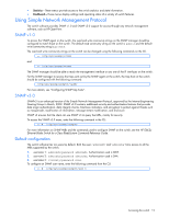
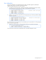
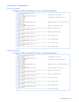
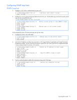
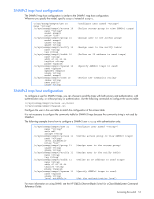
Configuring an IP interface An IP interface address must be set on the switch to provide management access to the switch over an IP network. By default, the management interface is set up to request its IP address from a Bootstrap Protocol (BOOTP) server. If you have a BOOTP server on your network, add the Media Access Control (MAC) address of the switch to the BOOTP configuration file located on the BOOTP server. The MAC address can be found on a small white label on the back panel of the switch. The MAC address can also be found in the System Information menu (see the HP GbE2c Ethernet Blade Switch for c-Class BladeSystem Command Reference Guide or ISCLI Guide.) If you are using a DHCP server that also does BOOTP, you do not have to configure the MAC address. If you do not have a BOOTP server, you must manually configure an IP address. The following example shows how to manually configure an IP address on the switch: 1. Configure an IP interface for the Telnet connection, using the sample IP address of 205.21.17.3. 2. The pending subnet mask address and broadcast address are automatically calculated. >> # /cfg/l3/if 1 (Select IP interface 1) >> IP Interface 1# addr 205.21.17.3 (Assign IP address for the interface) Current IP address: 0.0.0.0 New pending IP address: 205.21.17.3 Pending new subnet mask: 255.255.255.0 >> IP Interface 1# ena (Enable IP interface 1) 3. If necessary, configure up to two default gateways. 4. Configuring the default gateways allows the switch to send outbound traffic to the routers. >> IP Interface 5# ../gw 1 (Select primary default gateway) >> Default gateway 1# addr 205.21.17.1 (Assign IP address for primary router) >> Default gateway 1# ena (Enable primary default gateway) >> Default gateway 1# ../gw 2 (Select secondary default gateway) >> Default gateway 2# addr 205.21.17.2 >> Default gateway 2# ena (Assign address for secondary router) (Enable secondary default gateway) 5. Apply, verify, and save the configuration. >> Default gateway 2# apply >> Default gateway 2# save >> # /cfg/dump (Apply the configuration) (Save the configuration) (Verify the configuration) Using the Browser-based Interface By default, the Browser-based Interface (BBI) protocol is enabled on the switch. The Browser-based Interface (BBI) provides access to the common configuration, management and operation features of the switch through your Web browser. For more information, see the HP GbE2c Ethernet Blade Switch for c-Class BladeSystem Browser-based Interface Reference Guide. The BBI is organized at a high level as follows: • Configuration-These menus provide access to the configuration elements for the entire switch. • System-Configure general switch configuration elements. • Switch ports-Configure switch ports and related features. • Port-based port mirroring-Configure mirrored ports and monitoring ports. • Layer 2-Configure Layer 2 features, including trunk groups, VLANs, and Spanning Tree Protocol. • RMON menu-Configure Remote Monitoring (RMON) functions. • Layer 3-Configure all of the IP related information, including IGMP Snooping. • QoS-Configure Quality of Service features. • Access Control-Configure Access Control Lists and Groups. • Uplink Failure Detection-Configure a Failover Pair of Links to Monitor and Links to Disable. Accessing the switch 11
-
 1
1 -
2
-
3
-
4
-
5
-
 6
6 -
 7
7 -
 8
8 -
 9
9 -
 10
10 -
 11
11 -
 12
12 -
 13
13 -
 14
14 -
 15
15 -
 16
16 -
17
-
18
-
19
-
20
-
21
-
22
-
23
-
24
-
25
-
26
-
27
-
28
-
29
-
30
-
31
-
32
-
33
-
34
-
35
-
36
-
37
-
38
-
39
-
40
-
41
-
42
-
43
-
44
-
45
-
46
-
47
-
48
-
49
-
50
-
51
-
52
-
53
-
54
-
55
-
56
-
57
-
58
-
59
-
60
-
61
-
62
-
63
-
64
-
65
-
66
-
67
-
68
-
69
-
70
-
71
-
72
-
73
-
74
-
75
-
76
-
77
-
78
-
79
-
80
-
81
-
82
-
83
-
84
-
85
-
86
-
87
-
88
-
89
-
90
-
91
-
92
-
93
-
94
-
95
-
96
-
97
-
98
-
99
-
100
-
101
-
102
-
103
-
104
-
105
-
106
-
107
-
108
-
109
-
110
-
111
-
112
-
113
-
114
-
115
-
116
-
117
-
118
-
119
-
120
-
121
-
122
-
123
-
124
-
125
-
126
-
127
-
128
-
129
-
130
-
131
-
132
-
133
-
134
-
135
-
136
-
137
-
138
-
139
-
140
-
141
-
142
-
143
-
144
-
145
-
146
-
147
-
148
-
149
-
150
-
151
-
152
-
153
-
154
-
155
-
156
-
157
-
158
-
159
-
160
-
161
-
162
-
163
-
164
-
165
 |
 |