HP GbE2c HP GbE2c Ethernet Blade Switch for c-Class BladeSystem Application Gu - Page 65
Multiple Spanning Tree Protocol, MSTP region, Common Internal Spanning Tree
 |
UPC - 808736802215
View all HP GbE2c manuals
Add to My Manuals
Save this manual to your list of manuals |
Page 65 highlights
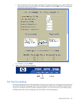
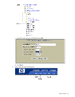
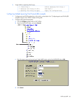
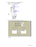
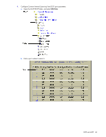
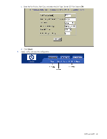
Multiple Spanning Tree Protocol IEEE 802.1s Multiple Spanning Tree extends the IEEE 802.1w Rapid Spanning Tree Protocol through multiple Spanning Tree Groups. MSTP maintains up to 128 spanning-tree instances that correspond to STP Groups 1-128. In Multiple Spanning Tree Protocol (MSTP), several VLANs can be mapped to each Spanning-Tree instance. Each Spanning-Tree instance is independent of other instances. MSTP allows frames assigned to different VLANs to follow separate paths, each path based on an independent Spanning-Tree instance. This approach provides multiple forwarding paths for data traffic, enabling load balancing, and reducing the number of Spanning-Tree instances required to support a large number of VLANs. MSTP region A group of interconnected bridges that share the same attributes is called an MST region. Each bridge within the region must share the following attributes: • Alphanumeric name • Revision level • VLAN-to-STG mapping scheme MSTP provides rapid reconfiguration, scalability, and control due to the support of regions, and multiple SpanningTree instances support within each region. Common Internal Spanning Tree The Common Internal Spanning Tree (CIST) provides a common form of Spanning Tree Protocol, with one Spanning Tree instance that can be used throughout the MSTP region. CIST allows the switch to interoperate with legacy equipment, including devices that run IEEE 802.1d (STP). CIST allows the MSTP region to act as a virtual bridge to other bridges outside of the region, and provides a single Spanning-Tree instance to interact with them. CIST is the default spanning tree group. When VLANs are removed from STG 1-128, the VLANs automatically become members of the CIST. CIST port configuration includes Hello time, Edge port status (enable/disable), and Link Type. These parameters do not affect Spanning Tree Groups 1-128. They apply only when the CIST is used. MSTP configuration guidelines This section provides important information about configuring Multiple Spanning Tree Groups: • When you turn on MSTP, the switch automatically moves VLAN 1 to the Common Internal Spanning Tree (CIST). • Region Name and revision level must be configured. Each bridge in the region must have the same name and revision level. • The VLAN and STP Group mapping must be the same across all bridges in the region. • You can move any VLAN to the CIST. • You can move VLAN 1 into any Spanning Tree Group. MSTP configuration example This section provides steps to configure Multiple Spanning Tree Protocol on the switch, using the Command Line Interface (CLI) or the Browser-based Interface (BBI). Configuring Multiple Spanning Tree Protocol (CLI example) 1. Configure port and VLAN membership on the switch, as described in the "Configuring ports and VLANs (CLI example)" section in the "VLANs" chapter of this guide. 2. Set the mode to Multiple Spanning Tree, and configure MSTP region parameters. >> /cfg/l2/ mrst (Select Multiple Spanning Tree menu) >> Multiple Spanning Tree# mode mstp (Set mode to Multiple Spanning Trees) >> Multiple Spanning Tree# on (Turn Multiple Spanning Trees on) >> Multiple Spanning Tree# name xxxxxx (Define the Region name) >> Multiple Spanning Tree: rev xx (Define the Region revision level) RSTP and MSTP 65
-
 1
1 -
2
-
3
-
4
-
5
-
6
-
7
-
8
-
9
-
10
-
11
-
12
-
13
-
14
-
15
-
16
-
17
-
18
-
19
-
20
-
21
-
22
-
23
-
24
-
25
-
26
-
27
-
28
-
29
-
30
-
31
-
32
-
33
-
34
-
35
-
36
-
37
-
38
-
39
-
40
-
41
-
42
-
43
-
44
-
45
-
46
-
47
-
48
-
49
-
50
-
51
-
52
-
53
-
54
-
55
-
56
-
57
-
58
-
59
-
 60
60 -
 61
61 -
 62
62 -
 63
63 -
 64
64 -
 65
65 -
 66
66 -
 67
67 -
 68
68 -
 69
69 -
 70
70 -
71
-
72
-
73
-
74
-
75
-
76
-
77
-
78
-
79
-
80
-
81
-
82
-
83
-
84
-
85
-
86
-
87
-
88
-
89
-
90
-
91
-
92
-
93
-
94
-
95
-
96
-
97
-
98
-
99
-
100
-
101
-
102
-
103
-
104
-
105
-
106
-
107
-
108
-
109
-
110
-
111
-
112
-
113
-
114
-
115
-
116
-
117
-
118
-
119
-
120
-
121
-
122
-
123
-
124
-
125
-
126
-
127
-
128
-
129
-
130
-
131
-
132
-
133
-
134
-
135
-
136
-
137
-
138
-
139
-
140
-
141
-
142
-
143
-
144
-
145
-
146
-
147
-
148
-
149
-
150
-
151
-
152
-
153
-
154
-
155
-
156
-
157
-
158
-
159
-
160
-
161
-
162
-
163
-
164
-
165
 |
 |