HP GbE2c HP GbE2c Ethernet Blade Switch for c-Class BladeSystem Application Gu - Page 125
>> Open Shortest Path First # aindex 0, Enable OSPF.
 |
UPC - 808736802215
View all HP GbE2c manuals
Add to My Manuals
Save this manual to your list of manuals |
Page 125 highlights
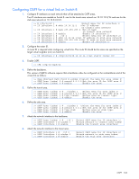
In this example, two IP interfaces are needed on Switch A: one for the backbone network on 10.10.7.0/24 and one for the transit area network on 10.10.12.0/24. >> # /cfg/l3/if 1 (Select menu for IP interface 1) >> IP Interface 1 # addr 10.10.7.1 (Set IP address on backbone network) >> IP Interface 1 # mask 255.255.255.0 (Set IP mask on backbone network) >> IP Interface 1 # enable (Enable IP interface 1) >> IP Interface 1 # ../if 2 (Select menu for IP interface 2) >> IP Interface 2 # addr 10.10.12.1 (Set IP address on transit area network) >> IP Interface 2 # mask 255.255.255.0 (Set IP mask on transit area network) >> IP Interface 2 # enable (Enable interface 2) 2. Configure the router ID. A router ID is required when configuring virtual links. Later, when configuring the other end of the virtual link on Switch B, the router ID specified here will be used as the target virtual neighbor (nbr) address >> IP Interface 2 # /cfg/l3/rtrid 10.10.10.1 (Set static router ID) 3. Enable OSPF. >> IP # /cfg/l3/ospf/on 4. Define the backbone. >> Open Shortest Path First # aindex 0 (Select menu for area index 0) >> OSPF Area (index) 0 # areaid 0.0.0.0 (Set the area ID) >> OSPF Area (index) 0 # type transit (Define backbone as transit type) >> OSPF Area (index) 0 # enable (Enable the area) 5. Define the transit area. The area that contains the virtual link must be configured as a transit area >> OSPF Area (index) 0 # ../aindex 1 (Select menu for area index 1) >> OSPF Area (index) 1 # areaid 0.0.0.1(Set the area ID for OSPF area 1) >> OSPF Area (index) 1 # type transit (Define area as transit type) >> OSPF Area (index) 1 # enable (Enable the area) 6. Attach the network interface to the backbone. >> OSPF Area (index) 1 # ../if 1 >> OSPF Interface 1 # aindex 0 >> OSPF Interface 1 # enable (Select OSPF menu for IP interface 1) (Attach network to backbone index) (Enable the backbone interface) 7. Attach the network interface to the transit area. >> OSPF Interface 1 # ../if 2 >> OSPF Interface 2 # aindex 1 >> OSPF Interface 2 # enable (Select OSPF menu for IP interface 2) (Attach network to transit area index) (Enable the transit area interface) 8. Configure the virtual link. The nbr router ID configured in this step must be the same as the router ID that will be configured for Switch B in step 2. >> OSPF Interface 2 # ../virt 1 (Specify a virtual link number) >> OSPF Virtual Link 1 # aindex 1 (Specify the transit area for the virtual link) >> OSPF Virtual Link 1 # nbr 10.10.14.1 (Specify the router ID of the recipient) >> OSPF Virtual Link 1 # enable (Enable the virtual link) 9. Apply and save the configuration changes >> OSPF Interface 2 # apply >> OSPF Interface 2 # save (Apply all changes) (Save all changes) OSPF 125
-
 1
1 -
2
-
3
-
4
-
5
-
6
-
7
-
8
-
9
-
10
-
11
-
12
-
13
-
14
-
15
-
16
-
17
-
18
-
19
-
20
-
21
-
22
-
23
-
24
-
25
-
26
-
27
-
28
-
29
-
30
-
31
-
32
-
33
-
34
-
35
-
36
-
37
-
38
-
39
-
40
-
41
-
42
-
43
-
44
-
45
-
46
-
47
-
48
-
49
-
50
-
51
-
52
-
53
-
54
-
55
-
56
-
57
-
58
-
59
-
60
-
61
-
62
-
63
-
64
-
65
-
66
-
67
-
68
-
69
-
70
-
71
-
72
-
73
-
74
-
75
-
76
-
77
-
78
-
79
-
80
-
81
-
82
-
83
-
84
-
85
-
86
-
87
-
88
-
89
-
90
-
91
-
92
-
93
-
94
-
95
-
96
-
97
-
98
-
99
-
100
-
101
-
102
-
103
-
104
-
105
-
106
-
107
-
108
-
109
-
110
-
111
-
112
-
113
-
114
-
115
-
116
-
117
-
118
-
119
-
 120
120 -
 121
121 -
 122
122 -
 123
123 -
 124
124 -
 125
125 -
 126
126 -
 127
127 -
 128
128 -
 129
129 -
 130
130 -
131
-
132
-
133
-
134
-
135
-
136
-
137
-
138
-
139
-
140
-
141
-
142
-
143
-
144
-
145
-
146
-
147
-
148
-
149
-
150
-
151
-
152
-
153
-
154
-
155
-
156
-
157
-
158
-
159
-
160
-
161
-
162
-
163
-
164
-
165
 |
 |