HP GbE2c HP GbE2c Ethernet Blade Switch for c-Class BladeSystem Application Gu - Page 32
Port trunking example, HP GbE2c Ethernet Blade, Switch for c-Class BladeSystem User Guide - configuration examples
 |
UPC - 808736802215
View all HP GbE2c manuals
Add to My Manuals
Save this manual to your list of manuals |
Page 32 highlights
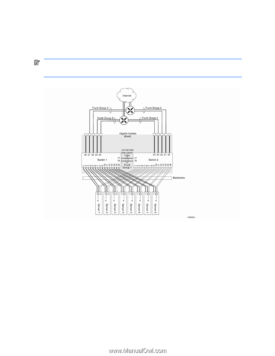
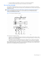
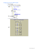
• You cannot configure a trunk member as a monitor port in a Port Mirroring configuration. • A monitor port cannot monitor trunks; however, trunk members can be monitored. Port trunking example In this example, the Gigabit uplink ports on each switch, and the crosslink ports are configured into a total of five trunk groups: two on each switch, and one trunk group at the crosslink between the two switches. All ports operate at Gigabit Ethernet speed. NOTE: The actual mapping of switch ports to NIC interfaces is dependant on the operating system software, the type of server blade, and the enclosure type. For more information, see the HP GbE2c Ethernet Blade Switch for c-Class BladeSystem User Guide. Figure 1 Port trunk group configuration example The trunk groups are configured as follows: • Trunk group 1 is configured by default on the crosslink ports 17 and 18, which connect the switches 1 and 2 together. Since this is the default configuration, you do not need to configure trunk group 1 on either switch. By default, ports 17 and 18 are disabled. • Trunk groups 2-5 consist of two Gigabit uplink ports each, configured to act as a single link to the upstream routers. The trunk groups on each switch are configured so that there is a link to each router for redundancy. Prior to configuring each switch in this example, you must connect to the appropriate switch CLI as the administrator. For details about accessing and using any of the commands described in this example, see the HP GbE2c Ethernet Blade Switch for c-Class BladeSystem Command Reference Guide. Ports and trunking 32
-
 1
1 -
2
-
3
-
4
-
5
-
6
-
7
-
8
-
9
-
10
-
11
-
12
-
13
-
14
-
15
-
16
-
17
-
18
-
19
-
20
-
21
-
22
-
23
-
24
-
25
-
26
-
 27
27 -
 28
28 -
 29
29 -
 30
30 -
 31
31 -
 32
32 -
 33
33 -
 34
34 -
 35
35 -
 36
36 -
 37
37 -
38
-
39
-
40
-
41
-
42
-
43
-
44
-
45
-
46
-
47
-
48
-
49
-
50
-
51
-
52
-
53
-
54
-
55
-
56
-
57
-
58
-
59
-
60
-
61
-
62
-
63
-
64
-
65
-
66
-
67
-
68
-
69
-
70
-
71
-
72
-
73
-
74
-
75
-
76
-
77
-
78
-
79
-
80
-
81
-
82
-
83
-
84
-
85
-
86
-
87
-
88
-
89
-
90
-
91
-
92
-
93
-
94
-
95
-
96
-
97
-
98
-
99
-
100
-
101
-
102
-
103
-
104
-
105
-
106
-
107
-
108
-
109
-
110
-
111
-
112
-
113
-
114
-
115
-
116
-
117
-
118
-
119
-
120
-
121
-
122
-
123
-
124
-
125
-
126
-
127
-
128
-
129
-
130
-
131
-
132
-
133
-
134
-
135
-
136
-
137
-
138
-
139
-
140
-
141
-
142
-
143
-
144
-
145
-
146
-
147
-
148
-
149
-
150
-
151
-
152
-
153
-
154
-
155
-
156
-
157
-
158
-
159
-
160
-
161
-
162
-
163
-
164
-
165
 |
 |