HP GbE2c HP GbE2c Ethernet Blade Switch for c-Class BladeSystem Application Gu - Page 113
Virtual links - target
 |
UPC - 808736802215
View all HP GbE2c manuals
Add to My Manuals
Save this manual to your list of manuals |
Page 113 highlights
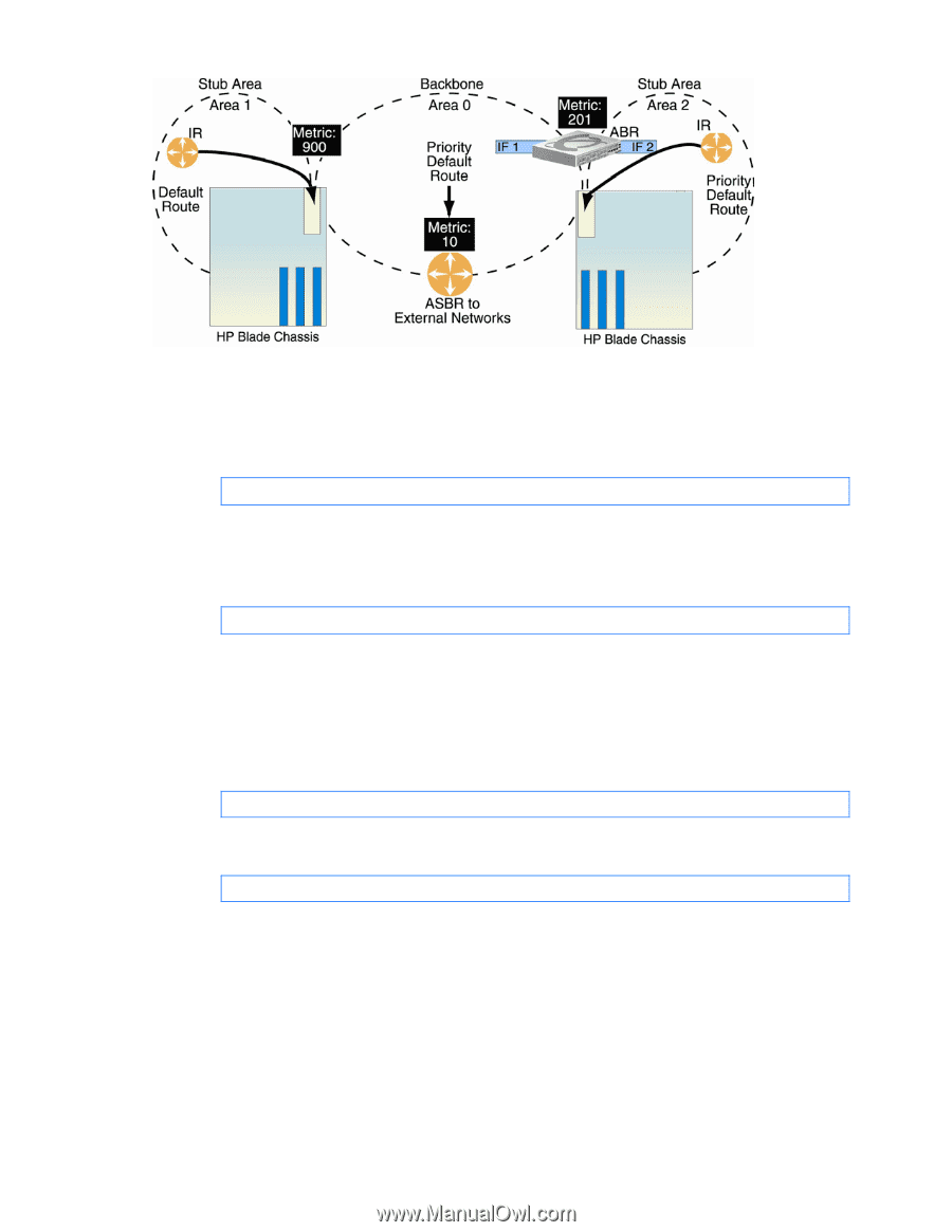
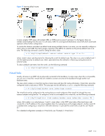
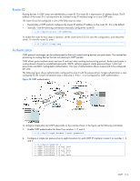
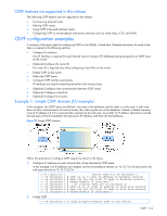
Figure 19 Injecting default routes In more complex OSPF areas with multiple ABRs or ASBRs (such as area 0 and area 2 in the figure), there are multiple routes leading from the area. In such areas, traffic for unrecognized destinations cannot tell which route leads upstream without further configuration. To resolve the situation and select one default route among multiple choices in an area, you can manually configure a metric value on each ABR. The metric assigns a priority to the ABR for its selection as the priority default route in an area. The following command is used for setting the metric value: >> # /cfg/l3/ospf/default where sets the priority for choosing this switch for default route. The value none sets no default and 1 sets the highest priority for default route. Metric type determines the method for influencing routing decisions for external routes. To clear a default route metric from the switch, use the following command: >> # /cfg/l3/ospf/default none Virtual links Usually, all areas in an OSPF AS are physically connected to the backbone. In some cases where this is not possible, you can use a virtual link. Virtual links are created to connect one area to the backbone through another nonbackbone area. The area which contains a virtual link must be a transit area and have full routing information. Virtual links cannot be configured inside a stub area or NSSA. The area type must be defined as transit using the following command: >> # /cfg/l3/ospf/aindex /type transit The virtual link must be configured on the routing devices at each endpoint of the virtual link, though they may traverse multiple routing devices. To configure a switch as one endpoint of a virtual link, use the following command: >> # /cfg/l3/ospf/virt /aindex /nbr where is a value between 1 and 3, is the OSPF area index of the transit area, and is the IP address of the virtual neighbor (nbr), the routing device at the target endpoint. Another router ID is needed when configuring a virtual link in the other direction. To provide the switch with a router ID, see "Router ID." For a detailed configuration example on Virtual Links, see "Example 2: Virtual Links." OSPF 113
-
 1
1 -
2
-
3
-
4
-
5
-
6
-
7
-
8
-
9
-
10
-
11
-
12
-
13
-
14
-
15
-
16
-
17
-
18
-
19
-
20
-
21
-
22
-
23
-
24
-
25
-
26
-
27
-
28
-
29
-
30
-
31
-
32
-
33
-
34
-
35
-
36
-
37
-
38
-
39
-
40
-
41
-
42
-
43
-
44
-
45
-
46
-
47
-
48
-
49
-
50
-
51
-
52
-
53
-
54
-
55
-
56
-
57
-
58
-
59
-
60
-
61
-
62
-
63
-
64
-
65
-
66
-
67
-
68
-
69
-
70
-
71
-
72
-
73
-
74
-
75
-
76
-
77
-
78
-
79
-
80
-
81
-
82
-
83
-
84
-
85
-
86
-
87
-
88
-
89
-
90
-
91
-
92
-
93
-
94
-
95
-
96
-
97
-
98
-
99
-
100
-
101
-
102
-
103
-
104
-
105
-
106
-
107
-
 108
108 -
 109
109 -
 110
110 -
 111
111 -
 112
112 -
 113
113 -
 114
114 -
 115
115 -
 116
116 -
 117
117 -
 118
118 -
119
-
120
-
121
-
122
-
123
-
124
-
125
-
126
-
127
-
128
-
129
-
130
-
131
-
132
-
133
-
134
-
135
-
136
-
137
-
138
-
139
-
140
-
141
-
142
-
143
-
144
-
145
-
146
-
147
-
148
-
149
-
150
-
151
-
152
-
153
-
154
-
155
-
156
-
157
-
158
-
159
-
160
-
161
-
162
-
163
-
164
-
165
 |
 |