HP GbE2c HP GbE2c Ethernet Blade Switch for c-Class BladeSystem Application Gu - Page 124
Example 2: Virtual links, Configuring OSPF for a virtual link on Switch
 |
UPC - 808736802215
View all HP GbE2c manuals
Add to My Manuals
Save this manual to your list of manuals |
Page 124 highlights
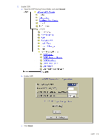
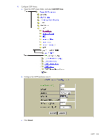
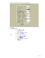
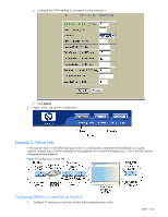
e. Configure the OSPF Interface 2, and attach it to the stub area 1. f. Click Submit. 6. Apply, verify, and save the configuration. Example 2: Virtual links In the example shown in the following figure, area 2 is not physically connected to the backbone as is usually required. Instead, area 2 will be connected to the backbone via a virtual link through area 1. The virtual link must be configured at each endpoint. Figure 22 Configuring a virtual link Configuring OSPF for a virtual link on Switch A 1. Configure IP interfaces on each network that will be attached to the switch. OSPF 124
-
 1
1 -
2
-
3
-
4
-
5
-
6
-
7
-
8
-
9
-
10
-
11
-
12
-
13
-
14
-
15
-
16
-
17
-
18
-
19
-
20
-
21
-
22
-
23
-
24
-
25
-
26
-
27
-
28
-
29
-
30
-
31
-
32
-
33
-
34
-
35
-
36
-
37
-
38
-
39
-
40
-
41
-
42
-
43
-
44
-
45
-
46
-
47
-
48
-
49
-
50
-
51
-
52
-
53
-
54
-
55
-
56
-
57
-
58
-
59
-
60
-
61
-
62
-
63
-
64
-
65
-
66
-
67
-
68
-
69
-
70
-
71
-
72
-
73
-
74
-
75
-
76
-
77
-
78
-
79
-
80
-
81
-
82
-
83
-
84
-
85
-
86
-
87
-
88
-
89
-
90
-
91
-
92
-
93
-
94
-
95
-
96
-
97
-
98
-
99
-
100
-
101
-
102
-
103
-
104
-
105
-
106
-
107
-
108
-
109
-
110
-
111
-
112
-
113
-
114
-
115
-
116
-
117
-
118
-
 119
119 -
 120
120 -
 121
121 -
 122
122 -
 123
123 -
 124
124 -
 125
125 -
 126
126 -
 127
127 -
 128
128 -
 129
129 -
130
-
131
-
132
-
133
-
134
-
135
-
136
-
137
-
138
-
139
-
140
-
141
-
142
-
143
-
144
-
145
-
146
-
147
-
148
-
149
-
150
-
151
-
152
-
153
-
154
-
155
-
156
-
157
-
158
-
159
-
160
-
161
-
162
-
163
-
164
-
165
 |
 |

OSPF 124
e.
Configure the OSPF Interface 2, and attach it to the stub area 1.
f.
Click
Submit
.
6.
Apply, verify, and save the configuration.
Example 2: Virtual links
In the example shown in the following figure, area 2 is not physically connected to the backbone as is usually
required. Instead, area 2 will be connected to the backbone via a virtual link through area 1. The virtual link must be
configured at each endpoint.
Figure 22
Configuring a virtual link
Configuring OSPF for a virtual link on Switch A
1.
Configure IP interfaces on each network that will be attached to the switch.