HP GbE2c HP GbE2c Ethernet Blade Switch for c-Class BladeSystem Application Gu - Page 48
Table 10, Multiple VLANs with VLAN tagging
 |
UPC - 808736802215
View all HP GbE2c manuals
Add to My Manuals
Save this manual to your list of manuals |
Page 48 highlights
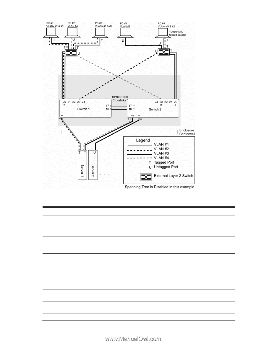
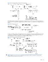
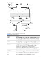
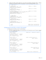
Figure 8 Multiple VLANs with VLAN tagging The features of this VLAN are described in the following table: Table 10 Multiple VLANs with tagging Component Description Switch 1 Switch 2 Blade Server #1 Blade Server #2 PC #1 PC #2 Switch 1 is configured for VLANS 1, 2, and 3. Port 1 is tagged to accept traffic from VLANs 1 and 2. Ports 17 and 18 are tagged members of a trunk that accepts traffic from VLANs 1 and 3. Port 20 is tagged to accept traffic from VLANs 1, 2, and 3. Port 23 is an untagged member of VLAN 2. Switch 2 is configured for VLANS 1, 3, and 4. Port 2 is tagged to accept traffic from VLANS 3 and 4. Port 4 is configured only for VLAN 3, so VLAN tagging is off. Port 20 is tagged to accept traffic from VLANs 1 and 3. Port 23 is an untagged member of VLAN 4. This high-use blade server needs to be accessed from all VLANs and IP subnets. The server has a VLAN-tagging adapter installed with VLAN tagging turned on. One adapter is attached to one of the switch's 10/100/1000 Mbps ports, that is configured for VLANs 1 and 2. One adapter is configured for VLANs 3 and 4. Because of the VLAN tagging capabilities of both the adapter and the switch, the server is able to communicate on all four VLANs in this network while maintaining broadcast separation among all four VLANs and subnets. This blade server belongs to VLAN 3. The port that the VLAN is attached to is configured only for VLAN 3, so VLAN tagging is off. This PC is a member of VLAN 2 and 3. Via VLAN 2, it can communicate with Server 1, PC 3, and PC 5. Via VLAN 3, it can communicate with Server 1, Server 2, and PC 4. This PC is a member of VLAN 4, and can only communicate with Server 1. VLANs 48
-
 1
1 -
2
-
3
-
4
-
5
-
6
-
7
-
8
-
9
-
10
-
11
-
12
-
13
-
14
-
15
-
16
-
17
-
18
-
19
-
20
-
21
-
22
-
23
-
24
-
25
-
26
-
27
-
28
-
29
-
30
-
31
-
32
-
33
-
34
-
35
-
36
-
37
-
38
-
39
-
40
-
41
-
42
-
 43
43 -
 44
44 -
 45
45 -
 46
46 -
 47
47 -
 48
48 -
 49
49 -
 50
50 -
 51
51 -
 52
52 -
 53
53 -
54
-
55
-
56
-
57
-
58
-
59
-
60
-
61
-
62
-
63
-
64
-
65
-
66
-
67
-
68
-
69
-
70
-
71
-
72
-
73
-
74
-
75
-
76
-
77
-
78
-
79
-
80
-
81
-
82
-
83
-
84
-
85
-
86
-
87
-
88
-
89
-
90
-
91
-
92
-
93
-
94
-
95
-
96
-
97
-
98
-
99
-
100
-
101
-
102
-
103
-
104
-
105
-
106
-
107
-
108
-
109
-
110
-
111
-
112
-
113
-
114
-
115
-
116
-
117
-
118
-
119
-
120
-
121
-
122
-
123
-
124
-
125
-
126
-
127
-
128
-
129
-
130
-
131
-
132
-
133
-
134
-
135
-
136
-
137
-
138
-
139
-
140
-
141
-
142
-
143
-
144
-
145
-
146
-
147
-
148
-
149
-
150
-
151
-
152
-
153
-
154
-
155
-
156
-
157
-
158
-
159
-
160
-
161
-
162
-
163
-
164
-
165
 |
 |