HP GbE2c HP GbE2c Ethernet Blade Switch for c-Class BladeSystem Application Gu - Page 148
Assigning VRRP virtual router ID, Configuring the switch for tracking - software upgrade
 |
UPC - 808736802215
View all HP GbE2c manuals
Add to My Manuals
Save this manual to your list of manuals |
Page 148 highlights
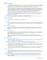
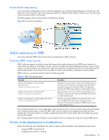
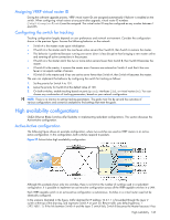
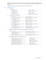
Assigning VRRP virtual router ID During the software upgrade process, VRRP virtual router IDs are assigned automatically if failover is enabled on the switch. When configuring virtual routers at any point after upgrade, virtual router ID numbers (/cfg/l3/vrrp/vr #/vrid) must be assigned. The virtual router ID may be configured as any number between 1 and 255. Configuring the switch for tracking Tracking configuration largely depends on user preferences and network environment. Consider the configuration shown in the previous figure. Assume the following behavior on the network: • Switch A is the master router upon initialization. • If Switch A is the master and it has one fewer active servers than Switch B, then Switch A remains the master. • This behavior is preferred because running one server down is less disruptive than bringing a new master online and severing all active connections in the process. • If Switch A is the master and it has two or more active servers fewer than Switch B, then Switch B becomes the master. • If Switch B is the master, it remains the master even if servers are restored on Switch A such that it has one fewer or an equal number of servers. • If Switch B is the master and it has one active server fewer than Switch A, then Switch A becomes the master. The user can implement this behavior by configuring the switch for tracking as follows: 1. Set the priority for Switch A to 101. 2. Leave the priority for Switch B at the default value of 100. 3. On both switches, enable tracking based on ports (ports), interfaces (ifs), or virtual routers (vr). You can choose any combination of tracking parameters, based on your network configuration. NOTE: There is no shortcut to setting tracking parameters. The goals must first be set and the outcomes of various configurations and scenarios analyzed to find settings that meet the goals. High availability configurations GbE2c Ethernet Blade Switches offer flexibility in implementing redundant configurations. This section discusses the Active-Active configuration. Active-Active configuration The following figure shows an example configuration, where two switches are used as VRRP routers in an activeactive configuration. In this configuration, both switches respond to packets. Figure 27 Active-Active high availability configuration Although this example shows only two switches, there is no limit on the number of switches used in a redundant configuration. It is possible to implement an active-active configuration across all the VRRP-capable switches in a LAN. Each VRRP-capable switch in an active-active configuration is autonomous. Switches in a virtual router need not be identically configured. In the scenario illustrated in the figure, traffic destined for IP address 10.0.1.1 is forwarded through the Layer 2 switch at the top of the drawing, and ingresses Switch A on port 20. Return traffic uses default gateway 1 (192.168.1.1). If the link between Switch A and the Layer 2 switch fails, Switch B becomes the Master because it has High availability 148
-
 1
1 -
2
-
3
-
4
-
5
-
6
-
7
-
8
-
9
-
10
-
11
-
12
-
13
-
14
-
15
-
16
-
17
-
18
-
19
-
20
-
21
-
22
-
23
-
24
-
25
-
26
-
27
-
28
-
29
-
30
-
31
-
32
-
33
-
34
-
35
-
36
-
37
-
38
-
39
-
40
-
41
-
42
-
43
-
44
-
45
-
46
-
47
-
48
-
49
-
50
-
51
-
52
-
53
-
54
-
55
-
56
-
57
-
58
-
59
-
60
-
61
-
62
-
63
-
64
-
65
-
66
-
67
-
68
-
69
-
70
-
71
-
72
-
73
-
74
-
75
-
76
-
77
-
78
-
79
-
80
-
81
-
82
-
83
-
84
-
85
-
86
-
87
-
88
-
89
-
90
-
91
-
92
-
93
-
94
-
95
-
96
-
97
-
98
-
99
-
100
-
101
-
102
-
103
-
104
-
105
-
106
-
107
-
108
-
109
-
110
-
111
-
112
-
113
-
114
-
115
-
116
-
117
-
118
-
119
-
120
-
121
-
122
-
123
-
124
-
125
-
126
-
127
-
128
-
129
-
130
-
131
-
132
-
133
-
134
-
135
-
136
-
137
-
138
-
139
-
140
-
141
-
142
-
 143
143 -
 144
144 -
 145
145 -
 146
146 -
 147
147 -
 148
148 -
 149
149 -
 150
150 -
 151
151 -
 152
152 -
 153
153 -
154
-
155
-
156
-
157
-
158
-
159
-
160
-
161
-
162
-
163
-
164
-
165
 |
 |