HP GbE2c HP GbE2c Ethernet Blade Switch for c-Class BladeSystem Application Gu - Page 55
Spanning Tree Protocol, Introduction, Overview, Bridge Protocol Data Units - routing vlan
 |
UPC - 808736802215
View all HP GbE2c manuals
Add to My Manuals
Save this manual to your list of manuals |
Page 55 highlights
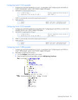
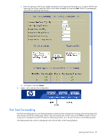
Spanning Tree Protocol Introduction When multiple paths exist on a network, Spanning Tree Protocol (STP) configures the network so that a switch uses only the most efficient path. The following topics are discussed in this chapter: • Overview • Bridge Protocol Data Units (BPDUs) • Spanning Tree Group (STG) configuration guidelines • Multiple Spanning Trees Overview Spanning Tree Protocol (STP) detects and eliminates logical loops in a bridged or switched network. STP forces redundant data paths into a standby (blocked) state. When multiple paths exist, STP configures the network so that a switch uses only the most efficient path. If that path fails, STP automatically sets up another active path on the network to sustain network operations. The switch supports IEEE 802.1d Spanning Tree Protocol for STG 1, and Per VLAN Spanning Tree Protocol (PVST+) for STGs 2-128, by default. NOTE: The switch also supports IEEE 802.1w Rapid Spanning Tree Protocol and IEEE 802.1s Multiple Spanning Tree Protocol. For more information, see the "RSTP and MSTP" chapter in this guide. Bridge Protocol Data Units To create a spanning tree, the application switch generates a configuration Bridge Protocol Data Unit (BPDU), which it then forwards out of its ports. All switches in the Layer 2 network participating in the spanning tree gather information about other switches in the network through an exchange of BPDUs. A BPDU is a 64-byte packet that is sent out at a configurable interval, which is typically set for two seconds. The BPDU is used to establish a path, much like a "hello" packet in IP routing. BPDUs contain information about the transmitting bridge and its ports, including bridge and MAC addresses, bridge priority, port priority, and port path cost. If the ports are tagged, each port sends out a special BPDU containing the tagged information. The generic action of a switch on receiving a BPDU is to compare the received BPDU to its own BPDU that it will transmit. If the received BPDU has a priority value closer to zero than its own BPDU, it will replace its BPDU with the received BPDU. Then, the application switch adds its own bridge ID number and increments the path cost of the BPDU. The application switch uses this information to block any redundant paths. Determining the path for forwarding BPDUs When determining which port to use for forwarding and which port to block, the switch uses information in the BPDU, including each bridge priority ID. A technique based on the "lowest root cost" is then computed to determine the most efficient path for forwarding. Bridge priority The bridge priority parameter controls which bridge on the network is the STP root bridge. To make one switch the root bridge, configure the bridge priority lower than all other switches and bridges on your network. The lower the value, the higher the bridge priority. The bridge priority is configured using the following command: /cfg/l2/stp x/brg/prior Port priority The port priority helps determine which bridge port becomes the designated port. In a network topology that has multiple bridge ports connected to a single segment, the port with the lowest port priority becomes the designated port for the segment. The port priority is configured using the following command: /cfg/l2/stp y/port x/prior Spanning Tree Protocol 55
-
 1
1 -
2
-
3
-
4
-
5
-
6
-
7
-
8
-
9
-
10
-
11
-
12
-
13
-
14
-
15
-
16
-
17
-
18
-
19
-
20
-
21
-
22
-
23
-
24
-
25
-
26
-
27
-
28
-
29
-
30
-
31
-
32
-
33
-
34
-
35
-
36
-
37
-
38
-
39
-
40
-
41
-
42
-
43
-
44
-
45
-
46
-
47
-
48
-
49
-
 50
50 -
 51
51 -
 52
52 -
 53
53 -
 54
54 -
 55
55 -
 56
56 -
 57
57 -
 58
58 -
 59
59 -
 60
60 -
61
-
62
-
63
-
64
-
65
-
66
-
67
-
68
-
69
-
70
-
71
-
72
-
73
-
74
-
75
-
76
-
77
-
78
-
79
-
80
-
81
-
82
-
83
-
84
-
85
-
86
-
87
-
88
-
89
-
90
-
91
-
92
-
93
-
94
-
95
-
96
-
97
-
98
-
99
-
100
-
101
-
102
-
103
-
104
-
105
-
106
-
107
-
108
-
109
-
110
-
111
-
112
-
113
-
114
-
115
-
116
-
117
-
118
-
119
-
120
-
121
-
122
-
123
-
124
-
125
-
126
-
127
-
128
-
129
-
130
-
131
-
132
-
133
-
134
-
135
-
136
-
137
-
138
-
139
-
140
-
141
-
142
-
143
-
144
-
145
-
146
-
147
-
148
-
149
-
150
-
151
-
152
-
153
-
154
-
155
-
156
-
157
-
158
-
159
-
160
-
161
-
162
-
163
-
164
-
165
 |
 |