HP GbE2c HP GbE2c Ethernet Blade Switch for c-Class BladeSystem Application Gu - Page 31
Port trunk groups, Statistical load distribution, Built-in fault tolerance - trunking
 |
UPC - 808736802215
View all HP GbE2c manuals
Add to My Manuals
Save this manual to your list of manuals |
Page 31 highlights
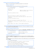
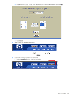
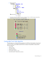
Port trunk groups When using port trunk groups between two switches, you can create an aggregate link operating at up to five Gigabits per second, depending on how many physical ports are combined. The switch supports up to 12 trunk groups per switch, each with up to six ports per trunk group. The trunking software detects broken trunk links (link down or disabled) and redirects traffic to other trunk members within that trunk group. You can only use trunking if each link has the same configuration for speed, flow control, and auto-negotiation. Statistical load distribution In a configured trunk group containing more than one port, the load distribution is determined by information embedded within the data frame. For IP traffic, the switch will calculate the trunk port to use for forwarding traffic by implementing the load distribution algorithm on value equals to modulus of (XOR of last 3 bits of Source and last 3 bits of Destination IP address). For non-IP traffic, the switch will calculate the trunk port to use for forwarding traffic by implementing the load distribution algorithm on value equals to modulus of (XOR of last 3 bits of Source and last 3 bits of Destination MAC address). Built-in fault tolerance Since each trunk group is composed of multiple physical links, the trunk group is inherently fault tolerant. As long as even one physical link between the switches is available, the trunk remains active. Statistical load distribution is maintained whenever a link in a trunk group is lost or returned to service. Before you configure trunks When you create and enable a trunk, the trunk members (switch ports) take on certain settings necessary for correct operation of the trunking feature. Before you configure your trunk, you must consider these settings, along with specific configuration rules, as follows: 1. Read the configuration rules provided in the "Trunk group configuration rules" section. 2. Determine which switch ports (up to six) are to become trunk members (the specific ports making up the trunk). 3. Ensure that the chosen switch ports are set to enabled, using the /cfg/port command. 4. Trunk member ports must have the same VLAN configuration. 5. Consider how the existing spanning tree will react to the new trunk configuration. See the "Spanning Tree Protocol" chapter for spanning tree group configuration guidelines. 6. Consider how existing VLANs will be affected by the addition of a trunk. Trunk group configuration rules The trunking feature operates according to specific configuration rules. When creating trunks, consider the following rules that determine how a trunk group reacts in any network topology: • All trunks must originate from one device, and lead to one destination device. For example, you cannot combine a link from Server 1 and a link from Server 2 into one trunk group. • Any physical switch port can belong to only one trunk group. • Trunking from non-HP devices must comply with Cisco® EtherChannel® technology. • All trunk member ports must be assigned to the same VLAN configuration before the trunk can be enabled. • All trunk member ports must be set to full duplex mode. • All trunk member ports must be configured for the same speed. • If you change the VLAN settings of any trunk member, you cannot apply the change until you change the VLAN settings of all trunk members. • When an active port is configured in a trunk, the port becomes a trunk member when you enable the trunk using the /cfg/l2/trunk x/ena command. The spanning tree parameters for the port then change to reflect the new trunk settings. • All trunk members must be in the same spanning tree group and can belong to only one spanning tree group. However if all ports are tagged, then all trunk ports can belong to multiple spanning tree groups. • When a trunk is enabled, the trunk spanning tree participation setting takes precedence over that of any trunk member. Ports and trunking 31
-
 1
1 -
2
-
3
-
4
-
5
-
6
-
7
-
8
-
9
-
10
-
11
-
12
-
13
-
14
-
15
-
16
-
17
-
18
-
19
-
20
-
21
-
22
-
23
-
24
-
25
-
 26
26 -
 27
27 -
 28
28 -
 29
29 -
 30
30 -
 31
31 -
 32
32 -
 33
33 -
 34
34 -
 35
35 -
 36
36 -
37
-
38
-
39
-
40
-
41
-
42
-
43
-
44
-
45
-
46
-
47
-
48
-
49
-
50
-
51
-
52
-
53
-
54
-
55
-
56
-
57
-
58
-
59
-
60
-
61
-
62
-
63
-
64
-
65
-
66
-
67
-
68
-
69
-
70
-
71
-
72
-
73
-
74
-
75
-
76
-
77
-
78
-
79
-
80
-
81
-
82
-
83
-
84
-
85
-
86
-
87
-
88
-
89
-
90
-
91
-
92
-
93
-
94
-
95
-
96
-
97
-
98
-
99
-
100
-
101
-
102
-
103
-
104
-
105
-
106
-
107
-
108
-
109
-
110
-
111
-
112
-
113
-
114
-
115
-
116
-
117
-
118
-
119
-
120
-
121
-
122
-
123
-
124
-
125
-
126
-
127
-
128
-
129
-
130
-
131
-
132
-
133
-
134
-
135
-
136
-
137
-
138
-
139
-
140
-
141
-
142
-
143
-
144
-
145
-
146
-
147
-
148
-
149
-
150
-
151
-
152
-
153
-
154
-
155
-
156
-
157
-
158
-
159
-
160
-
161
-
162
-
163
-
164
-
165
 |
 |