HP GbE2c HP GbE2c Ethernet Blade Switch for c-Class BladeSystem Application Gu - Page 89
Example of subnet routing, HP c-Class GbE2c Ethernet Blade Switch Command Reference Guide. - gigabit blade switches
 |
UPC - 808736802215
View all HP GbE2c manuals
Add to My Manuals
Save this manual to your list of manuals |
Page 89 highlights
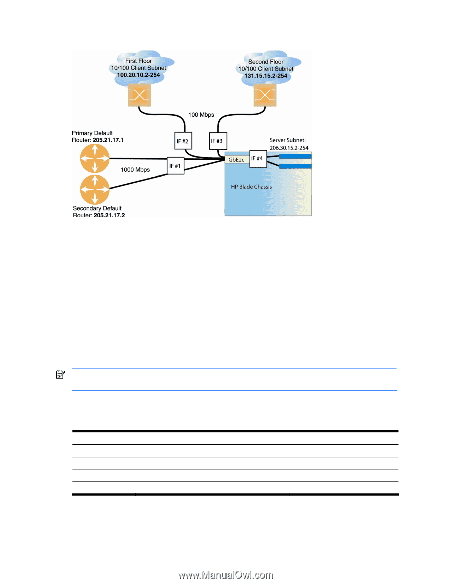
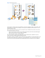
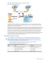
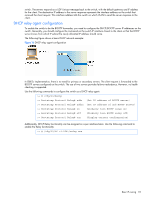
Take a closer look at the GbE2c in the following configuration example: Figure 15 Switch-based routing topology The GbE2c connects the Gigabit Ethernet and Fast Ethernet trunks from various switched subnets throughout one building. Common servers are placed on another subnet attached to the switch. Primary and backup routers are attached to the switch on yet another subnet. Without Layer 3 IP routing on the switch, cross-subnet communication is relayed to the default gateway (in this case, the router) for the next level of routing intelligence. The router fills in the necessary address information and sends the data back to the switch, which then relays the packet to the proper destination subnet using Layer 2 switching. With Layer 3 IP routing in place on the switch, routing between different IP subnets can be accomplished entirely within the switch. This leaves the routers free to handle inbound and outbound traffic for this group of subnets. To make implementation even easier, UDP Jumbo frame traffic is automatically fragmented to regular Ethernet frame sizes when routing to non-Jumbo frame VLANS or subnets. This automatic frame conversion allows servers to communicate using Jumbo frames, all transparently to the user. Example of subnet routing Prior to configuring, you must be connected to the switch Command Line Interface (CLI) as the administrator. NOTE: For details about accessing and using any of the menu commands described in this example, see the HP c-Class GbE2c Ethernet Blade Switch Command Reference Guide. 1. Assign an IP address (or document the existing one) for each router and client workstation. In the example topology, the following IP addresses are used: Table 021 Subnet routing example: IP address assignments Subnet Devices IP Addresses 1 Primary and Secondary Default Routers 205.21.17.1 and 205.21.17.2 2 First Floor Client Workstations 100.20.10.2-254 3 Second Floor Client Workstations 131.15.15.2-254 4 Common Servers 206.30.15.2-254 Basic IP routing 89
-
 1
1 -
2
-
3
-
4
-
5
-
6
-
7
-
8
-
9
-
10
-
11
-
12
-
13
-
14
-
15
-
16
-
17
-
18
-
19
-
20
-
21
-
22
-
23
-
24
-
25
-
26
-
27
-
28
-
29
-
30
-
31
-
32
-
33
-
34
-
35
-
36
-
37
-
38
-
39
-
40
-
41
-
42
-
43
-
44
-
45
-
46
-
47
-
48
-
49
-
50
-
51
-
52
-
53
-
54
-
55
-
56
-
57
-
58
-
59
-
60
-
61
-
62
-
63
-
64
-
65
-
66
-
67
-
68
-
69
-
70
-
71
-
72
-
73
-
74
-
75
-
76
-
77
-
78
-
79
-
80
-
81
-
82
-
83
-
 84
84 -
 85
85 -
 86
86 -
 87
87 -
 88
88 -
 89
89 -
 90
90 -
 91
91 -
 92
92 -
 93
93 -
 94
94 -
95
-
96
-
97
-
98
-
99
-
100
-
101
-
102
-
103
-
104
-
105
-
106
-
107
-
108
-
109
-
110
-
111
-
112
-
113
-
114
-
115
-
116
-
117
-
118
-
119
-
120
-
121
-
122
-
123
-
124
-
125
-
126
-
127
-
128
-
129
-
130
-
131
-
132
-
133
-
134
-
135
-
136
-
137
-
138
-
139
-
140
-
141
-
142
-
143
-
144
-
145
-
146
-
147
-
148
-
149
-
150
-
151
-
152
-
153
-
154
-
155
-
156
-
157
-
158
-
159
-
160
-
161
-
162
-
163
-
164
-
165
 |
 |