HP GbE2c HP GbE2c Ethernet Blade Switch for c-Class BladeSystem Application Gu - Page 45
Port-based VLAN assignment
 |
UPC - 808736802215
View all HP GbE2c manuals
Add to My Manuals
Save this manual to your list of manuals |
Page 45 highlights
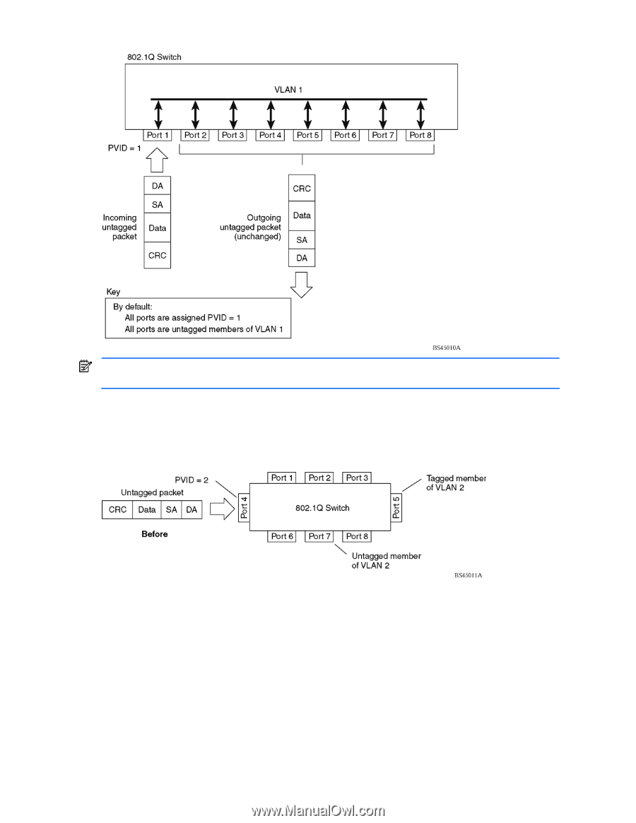
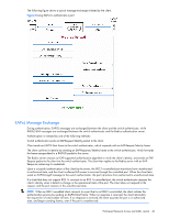
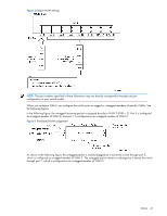
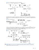
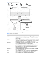
Figure 3 Default VLAN settings NOTE: The port numbers specified in these illustrations may not directly correspond to the physical port configuration of your switch model. When you configure VLANs, you configure the switch ports as tagged or untagged members of specific VLANs. See the following figures. In the following figure, the untagged incoming packet is assigned directly to VLAN 2 (PVID = 2). Port 5 is configured as a tagged member of VLAN 2, and port 7 is configured as an untagged member of VLAN 2. Figure 4 Port-based VLAN assignment As shown in the following figure, the untagged packet is marked (tagged) as it leaves the switch through port 5, which is configured as a tagged member of VLAN 2. The untagged packet remains unchanged as it leaves the switch through port 7, which is configured as an untagged member of VLAN 2. VLANs 45
-
 1
1 -
2
-
3
-
4
-
5
-
6
-
7
-
8
-
9
-
10
-
11
-
12
-
13
-
14
-
15
-
16
-
17
-
18
-
19
-
20
-
21
-
22
-
23
-
24
-
25
-
26
-
27
-
28
-
29
-
30
-
31
-
32
-
33
-
34
-
35
-
36
-
37
-
38
-
39
-
 40
40 -
 41
41 -
 42
42 -
 43
43 -
 44
44 -
 45
45 -
 46
46 -
 47
47 -
 48
48 -
 49
49 -
 50
50 -
51
-
52
-
53
-
54
-
55
-
56
-
57
-
58
-
59
-
60
-
61
-
62
-
63
-
64
-
65
-
66
-
67
-
68
-
69
-
70
-
71
-
72
-
73
-
74
-
75
-
76
-
77
-
78
-
79
-
80
-
81
-
82
-
83
-
84
-
85
-
86
-
87
-
88
-
89
-
90
-
91
-
92
-
93
-
94
-
95
-
96
-
97
-
98
-
99
-
100
-
101
-
102
-
103
-
104
-
105
-
106
-
107
-
108
-
109
-
110
-
111
-
112
-
113
-
114
-
115
-
116
-
117
-
118
-
119
-
120
-
121
-
122
-
123
-
124
-
125
-
126
-
127
-
128
-
129
-
130
-
131
-
132
-
133
-
134
-
135
-
136
-
137
-
138
-
139
-
140
-
141
-
142
-
143
-
144
-
145
-
146
-
147
-
148
-
149
-
150
-
151
-
152
-
153
-
154
-
155
-
156
-
157
-
158
-
159
-
160
-
161
-
162
-
163
-
164
-
165
 |
 |