HP GbE2c HP GbE2c Ethernet Blade Switch for c-Class BladeSystem Application Gu - Page 57
Adding and removing ports from STGs, Assigning cost to ports and trunk groups, Multiple Spanning Trees - rstp enable
 |
UPC - 808736802215
View all HP GbE2c manuals
Add to My Manuals
Save this manual to your list of manuals |
Page 57 highlights
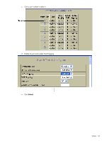
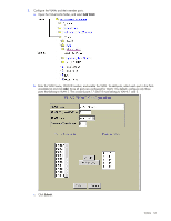
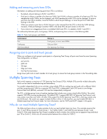
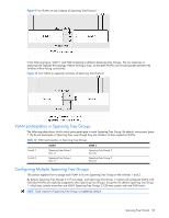
Adding and removing ports from STGs Information on adding and removing ports from STGs is as follows: • By default, all ports belong to VLAN 1 and STG 1. • Each port is always a member of at least one VLAN. Each VLAN is always a member of at least one STG. Port membership within VLANs can be changed, and VLAN membership within STGs can be changed. To move a port from one STG to another, move the VLAN to which the port belongs, or move the port to a VLAN that belongs to the STG. • When you remove a port from a VLAN, that port is also removed from the STG to which the VLAN belongs. However, if that port belongs to another VLAN in the same STG, the port remains in the STG. • If you remove an untagged port from a non-default VLAN and STG, it is added to VLAN 1 and STG 1. The relationship between ports, trunk groups, VLANs, and spanning trees is shown in the following table. Table 11 Ports, trunk groups, and VLANs Switch element Belongs to Port Trunk group VLAN (non-default) Trunk group, or one or more VLANs Only one VLAN One Spanning Tree Group Assigning cost to ports and trunk groups When you configure a trunk group to participate in a Spanning Tree Group, all ports must have the same Spanning Tree configuration, as follows: • port priority • path cost • link type • Edge port status • Port Fast Forward status Assign lower path costs on each member of a trunk group, to ensure the trunk group remains in the Forwarding state. Multiple Spanning Trees Each switch supports a maximum of 128 Spanning Tree Groups (STGs). Multiple STGs provide multiple data paths, which can be used for load-balancing and redundancy. You enable independent links on two switches using multiple STGs by configuring each path with a different VLAN and then assigning each VLAN to a separate STG. Each STG is independent. Each STG sends its own Bridge Protocol Data Units (BPDUs), and each STG must be independently configured. The STG, or bridge group, forms a loop-free topology that includes one or more virtual LANs (VLANs). The switch supports 128 STGs running simultaneously. The default STG 1 supports IEEE 802.1d Spanning Tree Protocol, and may contain more than one VLAN. All other STGs support Per VLAN Spanning Tree (PVST+), and may contain only one VLAN each. The switch can support multiple VLANs in STGs 2-128; however, you must enable IEEE 802.1s Multiple Spanning Tree Protocol mode. For more information, see the "RSTP and MSTP" chapter in this guide. Why do we need Multiple Spanning Trees? The following figure shows a simple example of why we need multiple Spanning Trees. This example assumes that port 17 and 18 are not part of Trunk Group 1. Two VLANs (VLAN 1 and VLAN 2) exist between Switch 1 and Switch 2. If the same Spanning Tree Group is enabled on both switches, the switches see an apparent loop and block port 18 on Switch 2, which cuts off communication between the switches for VLAN 2. Spanning Tree Protocol 57
-
 1
1 -
2
-
3
-
4
-
5
-
6
-
7
-
8
-
9
-
10
-
11
-
12
-
13
-
14
-
15
-
16
-
17
-
18
-
19
-
20
-
21
-
22
-
23
-
24
-
25
-
26
-
27
-
28
-
29
-
30
-
31
-
32
-
33
-
34
-
35
-
36
-
37
-
38
-
39
-
40
-
41
-
42
-
43
-
44
-
45
-
46
-
47
-
48
-
49
-
50
-
51
-
 52
52 -
 53
53 -
 54
54 -
 55
55 -
 56
56 -
 57
57 -
 58
58 -
 59
59 -
 60
60 -
 61
61 -
 62
62 -
63
-
64
-
65
-
66
-
67
-
68
-
69
-
70
-
71
-
72
-
73
-
74
-
75
-
76
-
77
-
78
-
79
-
80
-
81
-
82
-
83
-
84
-
85
-
86
-
87
-
88
-
89
-
90
-
91
-
92
-
93
-
94
-
95
-
96
-
97
-
98
-
99
-
100
-
101
-
102
-
103
-
104
-
105
-
106
-
107
-
108
-
109
-
110
-
111
-
112
-
113
-
114
-
115
-
116
-
117
-
118
-
119
-
120
-
121
-
122
-
123
-
124
-
125
-
126
-
127
-
128
-
129
-
130
-
131
-
132
-
133
-
134
-
135
-
136
-
137
-
138
-
139
-
140
-
141
-
142
-
143
-
144
-
145
-
146
-
147
-
148
-
149
-
150
-
151
-
152
-
153
-
154
-
155
-
156
-
157
-
158
-
159
-
160
-
161
-
162
-
163
-
164
-
165
 |
 |