HP GbE2c HP GbE2c Ethernet Blade Switch for c-Class BladeSystem Application Gu - Page 49
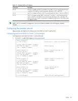
Configuring the example network, Configuring ports and VLANs on Switch 1 (CLI example) - layer 2 3 ethernet
 |
UPC - 808736802215
View all HP GbE2c manuals
Add to My Manuals
Save this manual to your list of manuals |
Page 49 highlights
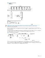
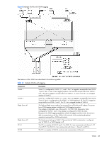
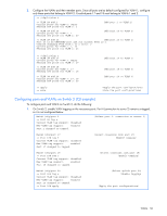
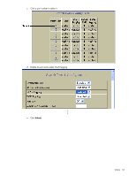
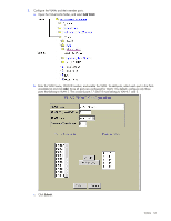
Table 10 Multiple VLANs with tagging Component PC #3 PC #4 PC #5 Description This PC is a member of VLAN 1 and VLAN 2. Via VLAN 1, it can communicate with Server 1 and PC 5. Via VLAN 2, it can communicate with Server 1, PC 1, and PC 5. This PC is a member of VLAN 3, and it can communicate with Server 1, Server 2, and PC 1. This PC is a member of both VLAN 1 and VLAN 2. Via VLAN 1, it can communicate with Server 1 and PC 3. Via VLAN 2, it can communicate with Server 1, PC 1, and PC 3. The Layer 2 switch port to which it is connected is configured for both VLAN 1 and VLAN 2 and has tagging enabled. NOTE: All PCs connected to a tagged port must have an Ethernet adapter with VLAN-tagging capability installed. Configuring the example network These examples describe how to configure ports and VLANs on Switch 1 and Switch 2. Configuring ports and VLANs on Switch 1 (CLI example) To configure ports and VLANs on Switch 1, do the following: 1. On Switch 1, enable VLAN tagging on the necessary ports. Main# /cfg/port 1 >> Port 1# tag e (Select port 1: connection to server 1) Current VLAN tag support: disabled New VLAN tag support: enabled Port 1 changed to tagged. (Enable tagging) Main# /cfg/port 17 >> Port 17# tag e Current VLAN tag support: disabled New VLAN tag support: enabled Port 17 changed to tagged. (Select crosslink link port 17) (Enable tagging) Main# /cfg/port 18 >> Port 18# tag e Current VLAN tag support: disabled New VLAN tag support: enabled Port 18 changed to tagged. (Select crosslink link port 18) (Enable tagging) Main# /cfg/port 20 >> Port 20# tag e Current VLAN tag support: disabled New VLAN tag support: enabled Port 20 changed to tagged. >> Port 20# apply (Select uplink port 20) (Enable tagging) (Apply the port configurations) VLANs 49
-
 1
1 -
2
-
3
-
4
-
5
-
6
-
7
-
8
-
9
-
10
-
11
-
12
-
13
-
14
-
15
-
16
-
17
-
18
-
19
-
20
-
21
-
22
-
23
-
24
-
25
-
26
-
27
-
28
-
29
-
30
-
31
-
32
-
33
-
34
-
35
-
36
-
37
-
38
-
39
-
40
-
41
-
42
-
43
-
 44
44 -
 45
45 -
 46
46 -
 47
47 -
 48
48 -
 49
49 -
 50
50 -
 51
51 -
 52
52 -
 53
53 -
 54
54 -
55
-
56
-
57
-
58
-
59
-
60
-
61
-
62
-
63
-
64
-
65
-
66
-
67
-
68
-
69
-
70
-
71
-
72
-
73
-
74
-
75
-
76
-
77
-
78
-
79
-
80
-
81
-
82
-
83
-
84
-
85
-
86
-
87
-
88
-
89
-
90
-
91
-
92
-
93
-
94
-
95
-
96
-
97
-
98
-
99
-
100
-
101
-
102
-
103
-
104
-
105
-
106
-
107
-
108
-
109
-
110
-
111
-
112
-
113
-
114
-
115
-
116
-
117
-
118
-
119
-
120
-
121
-
122
-
123
-
124
-
125
-
126
-
127
-
128
-
129
-
130
-
131
-
132
-
133
-
134
-
135
-
136
-
137
-
138
-
139
-
140
-
141
-
142
-
143
-
144
-
145
-
146
-
147
-
148
-
149
-
150
-
151
-
152
-
153
-
154
-
155
-
156
-
157
-
158
-
159
-
160
-
161
-
162
-
163
-
164
-
165
 |
 |