HP GbE2c HP GbE2c Ethernet Blade Switch for c-Class BladeSystem Application Gu - Page 112
Interface cost, Electing the designated router and backup, Summarizing routes, Default routes
 |
UPC - 808736802215
View all HP GbE2c manuals
Add to My Manuals
Save this manual to your list of manuals |
Page 112 highlights
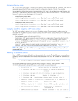
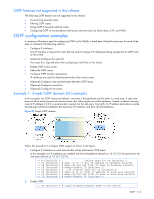
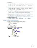
Interface cost The OSPF link-state algorithm (Dijkstra's algorithm) places each routing device at the root of a tree and determines the cumulative cost required to reach each destination. Usually, the cost is inversely proportional to the bandwidth of the interface. Low cost indicates high bandwidth. You can manually enter the cost for the output route with the following command: >> # /cfg/l3/ospf/if /cost Electing the designated router and backup In any area with more than two routing devices, a Designated Router (DR) is elected as the central contact for database exchanges among neighbors, and a Backup Designated Router (BDR) is elected in case the DR fails. DR and BDR elections are made through the hello process. The election can be influenced by assigning a priority value to the OSPF interfaces on the switch. The command is as follows: >>#/cfg/l3/ospf/if /prio A priority value of 255 is the highest, and 1 is the lowest. A priority value of 0 specifies that the interface cannot be used as a DR or BDR. In case of a tie, the routing device with the lowest router ID wins. Summarizing routes Route summarization condenses routing information. Without summarization, each routing device in an OSPF network would retain a route to every subnet in the network. With summarization, routing devices can reduce some sets of routes to a single advertisement, reducing both the load on the routing device and the perceived complexity of the network. The importance of route summarization increases with network size. Summary routes can be defined for up to 16 IP address ranges using the following command: >> # /cfg/l3/ospf/range /addr /mask where is a number 1 to 16, is the base IP address for the range, and is the IP address mask for the range. Default routes When an OSPF routing device encounters traffic for a destination address it does not recognize, it forwards that traffic along the default route. Typically, the default route leads upstream toward the backbone until it reaches the intended area or an external router. Each switch acting as an ABR automatically inserts a default route into each attached area. In simple OSPF stub areas or NSSAs with only one ABR leading upstream (see Area 1 in the figure below), any traffic for IP address destinations outside the area is forwarded to the switch's IP interface, and then into the connected transit area (usually the backbone). Since this is automatic, no further configuration is required for such areas. OSPF 112
-
 1
1 -
2
-
3
-
4
-
5
-
6
-
7
-
8
-
9
-
10
-
11
-
12
-
13
-
14
-
15
-
16
-
17
-
18
-
19
-
20
-
21
-
22
-
23
-
24
-
25
-
26
-
27
-
28
-
29
-
30
-
31
-
32
-
33
-
34
-
35
-
36
-
37
-
38
-
39
-
40
-
41
-
42
-
43
-
44
-
45
-
46
-
47
-
48
-
49
-
50
-
51
-
52
-
53
-
54
-
55
-
56
-
57
-
58
-
59
-
60
-
61
-
62
-
63
-
64
-
65
-
66
-
67
-
68
-
69
-
70
-
71
-
72
-
73
-
74
-
75
-
76
-
77
-
78
-
79
-
80
-
81
-
82
-
83
-
84
-
85
-
86
-
87
-
88
-
89
-
90
-
91
-
92
-
93
-
94
-
95
-
96
-
97
-
98
-
99
-
100
-
101
-
102
-
103
-
104
-
105
-
106
-
 107
107 -
 108
108 -
 109
109 -
 110
110 -
 111
111 -
 112
112 -
 113
113 -
 114
114 -
 115
115 -
 116
116 -
 117
117 -
118
-
119
-
120
-
121
-
122
-
123
-
124
-
125
-
126
-
127
-
128
-
129
-
130
-
131
-
132
-
133
-
134
-
135
-
136
-
137
-
138
-
139
-
140
-
141
-
142
-
143
-
144
-
145
-
146
-
147
-
148
-
149
-
150
-
151
-
152
-
153
-
154
-
155
-
156
-
157
-
158
-
159
-
160
-
161
-
162
-
163
-
164
-
165
 |
 |