HP GbE2c HP GbE2c Ethernet Blade Switch for c-Class BladeSystem Application Gu - Page 91
Using VLANs to segregate broadcast domains, Select VLAN 2
 |
UPC - 808736802215
View all HP GbE2c manuals
Add to My Manuals
Save this manual to your list of manuals |
Page 91 highlights
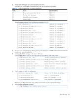
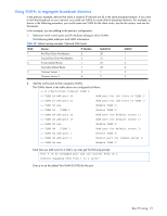
Using VLANs to segregate broadcast domains In the previous example, devices that share a common IP network are all in the same broadcast domain. If you want to limit the broadcasts on your network, you could use VLANs to create distinct broadcast domains. For example, as shown in the following procedure, you could create one VLAN for the client trunks, one for the routers, and one for the servers. In this example, you are adding to the previous configuration. 1. Determine which switch ports and IP interfaces belong to which VLANs. The following table adds port and VLAN information: Table 23 Subnet routing example: Optional VLAN ports VLAN Devices IP Interface Switch Port VLAN # 1 First Floor Client Workstations 2 20 1 Second Floor Client Workstations 3 21 1 2 Primary Default Router 1 22 2 Secondary Default Router 1 23 2 3 Common Servers 1 4 1 3 Common Servers 2 4 2 3 2. Add the switch ports to their respective VLANs. The VLANs shown in the table above are configured as follows: >> # /cfg/l2/vlan 1(Select VLAN 1) >> VLAN 1# add port 20 (Add port for 1st floor to VLAN 1) >> VLAN 1# add port 21 (Add port for 2nd floor to VLAN 1) >> VLAN 1# ena (Enable VLAN 1) >> VLAN 1# ../VLAN 2 (Select VLAN 2) >> VLAN 2# add port 22 (Add port for default router 1) >> VLAN 2# add port 23 (Add port for default router 2) >> VLAN 2# ena (Enable VLAN 2) >> VLAN 2# ../VLAN 3 (Add port for default router 3) >> VLAN 3# add port 1 (Select VLAN 3) >> VLAN 3# add port 2 (Select port for common server 1) >> VLAN 3# ena (Enable VLAN 3) Each time you add a port to a VLAN, you may get the following prompt: Port 4 is an untagged port and its current PVID is 1. Confirm changing PVID from 1 to 2 [y/n]? Enter y to set the default Port VLAN ID (PVID) for the port. Basic IP routing 91
-
 1
1 -
2
-
3
-
4
-
5
-
6
-
7
-
8
-
9
-
10
-
11
-
12
-
13
-
14
-
15
-
16
-
17
-
18
-
19
-
20
-
21
-
22
-
23
-
24
-
25
-
26
-
27
-
28
-
29
-
30
-
31
-
32
-
33
-
34
-
35
-
36
-
37
-
38
-
39
-
40
-
41
-
42
-
43
-
44
-
45
-
46
-
47
-
48
-
49
-
50
-
51
-
52
-
53
-
54
-
55
-
56
-
57
-
58
-
59
-
60
-
61
-
62
-
63
-
64
-
65
-
66
-
67
-
68
-
69
-
70
-
71
-
72
-
73
-
74
-
75
-
76
-
77
-
78
-
79
-
80
-
81
-
82
-
83
-
84
-
85
-
 86
86 -
 87
87 -
 88
88 -
 89
89 -
 90
90 -
 91
91 -
 92
92 -
 93
93 -
 94
94 -
 95
95 -
 96
96 -
97
-
98
-
99
-
100
-
101
-
102
-
103
-
104
-
105
-
106
-
107
-
108
-
109
-
110
-
111
-
112
-
113
-
114
-
115
-
116
-
117
-
118
-
119
-
120
-
121
-
122
-
123
-
124
-
125
-
126
-
127
-
128
-
129
-
130
-
131
-
132
-
133
-
134
-
135
-
136
-
137
-
138
-
139
-
140
-
141
-
142
-
143
-
144
-
145
-
146
-
147
-
148
-
149
-
150
-
151
-
152
-
153
-
154
-
155
-
156
-
157
-
158
-
159
-
160
-
161
-
162
-
163
-
164
-
165
 |
 |