HP Surestore Disk Array FC60 HP SureStore E Disk Array FC60 Service Manual (A5 - Page 142
Configuration Switches, Disk Enclosure (Tray) ID Switch
 |
View all HP Surestore Disk Array FC60 manuals
Add to My Manuals
Save this manual to your list of manuals |
Page 142 highlights
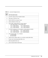
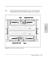
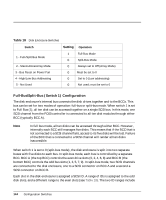
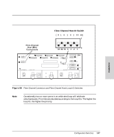
Configuration Switches This section describes the configuration switches on the controller enclosure and the disk enclosures. Configuration switch settings must be set to support the configuration (full-bus ore split-bus) being installed (as planned for from chapter 2, Topology and Array Planning). Controller enclosure and the disk enclosures configuration switches include: - Disk enclosure (Tray) ID switches - Disk enclosure DIP switches - Controller enclosure Fibre Channel host ID address switches Tips for Setting Configuration Switches • All switch settings should be the same on both BCC modules on the disk enclosures. • Disk enclosures must be power cycled before the new switch setting will take effect. • If a BCC is installed that has settings different than its peer, a buzzer will sound. The settings must be corrected to use the disk enclosure. Disk Enclosure (Tray) ID Switch The disk enclosure ID switch sets the Enclosure ID (or Tray ID). This value is used by FC60 diagnostic software and the controller to identify the disk enclosure for status monitoring operations. Each enclosure in the array must be set to a different Enclosure ID. To set the ID, set the rotary ID switches on the back of both BCC modules to the same number. See Figure 55. Typically, the disk enclosure closest to the controller enclosure is set to "0", the next one down to "1", and so on down the rack. See "How are disk modules in the array identified?" on page 190 for additional disk module addressing information.) Disk Enclosure DIP Switch A DIP switch located on the back of each BCC is used to set configuration options for BCC operation. See Figure 55. These DIP switches contain five switch segments. Switch segment 1 is used to select either split-bus or full-bus operation. See "Full-Bus/Split-Bus (Switch 1) Configuration" on page 144. The remaining four switch segments are not used for disk array operation and must always be set to "0." 142 Configuration Switches
-
 1
1 -
2
-
3
-
4
-
5
-
6
-
7
-
8
-
9
-
10
-
11
-
12
-
13
-
14
-
15
-
16
-
17
-
18
-
19
-
20
-
21
-
22
-
23
-
24
-
25
-
26
-
27
-
28
-
29
-
30
-
31
-
32
-
33
-
34
-
35
-
36
-
37
-
38
-
39
-
40
-
41
-
42
-
43
-
44
-
45
-
46
-
47
-
48
-
49
-
50
-
51
-
52
-
53
-
54
-
55
-
56
-
57
-
58
-
59
-
60
-
61
-
62
-
63
-
64
-
65
-
66
-
67
-
68
-
69
-
70
-
71
-
72
-
73
-
74
-
75
-
76
-
77
-
78
-
79
-
80
-
81
-
82
-
83
-
84
-
85
-
86
-
87
-
88
-
89
-
90
-
91
-
92
-
93
-
94
-
95
-
96
-
97
-
98
-
99
-
100
-
101
-
102
-
103
-
104
-
105
-
106
-
107
-
108
-
109
-
110
-
111
-
112
-
113
-
114
-
115
-
116
-
117
-
118
-
119
-
120
-
121
-
122
-
123
-
124
-
125
-
126
-
127
-
128
-
129
-
130
-
131
-
132
-
133
-
134
-
135
-
136
-
 137
137 -
 138
138 -
 139
139 -
 140
140 -
 141
141 -
 142
142 -
 143
143 -
 144
144 -
 145
145 -
 146
146 -
 147
147 -
148
-
149
-
150
-
151
-
152
-
153
-
154
-
155
-
156
-
157
-
158
-
159
-
160
-
161
-
162
-
163
-
164
-
165
-
166
-
167
-
168
-
169
-
170
-
171
-
172
-
173
-
174
-
175
-
176
-
177
-
178
-
179
-
180
-
181
-
182
-
183
-
184
-
185
-
186
-
187
-
188
-
189
-
190
-
191
-
192
-
193
-
194
-
195
-
196
-
197
-
198
-
199
-
200
-
201
-
202
-
203
-
204
-
205
-
206
-
207
-
208
-
209
-
210
-
211
-
212
-
213
-
214
-
215
-
216
-
217
-
218
-
219
-
220
-
221
-
222
-
223
-
224
-
225
-
226
-
227
-
228
-
229
-
230
-
231
-
232
-
233
-
234
-
235
-
236
-
237
-
238
-
239
-
240
-
241
-
242
-
243
-
244
-
245
-
246
-
247
-
248
-
249
-
250
-
251
-
252
-
253
-
254
-
255
-
256
-
257
-
258
-
259
-
260
-
261
-
262
-
263
-
264
-
265
-
266
-
267
-
268
-
269
-
270
-
271
-
272
-
273
-
274
-
275
-
276
-
277
-
278
-
279
-
280
-
281
-
282
-
283
-
284
-
285
-
286
-
287
-
288
-
289
-
290
-
291
-
292
-
293
-
294
-
295
-
296
-
297
-
298
-
299
-
300
-
301
-
302
-
303
-
304
-
305
-
306
-
307
-
308
-
309
-
310
-
311
-
312
-
313
-
314
-
315
-
316
-
317
-
318
-
319
-
320
-
321
-
322
-
323
-
324
-
325
-
326
-
327
-
328
-
329
-
330
-
331
-
332
-
333
-
334
-
335
-
336
-
337
-
338
-
339
-
340
-
341
-
342
-
343
-
344
-
345
-
346
-
347
-
348
-
349
-
350
-
351
-
352
-
353
-
354
-
355
-
356
-
357
-
358
-
359
-
360
-
361
-
362
-
363
-
364
-
365
-
366
-
367
-
368
-
369
-
370
-
371
-
372
-
373
-
374
-
375
-
376
-
377
-
378
-
379
-
380
-
381
-
382
-
383
-
384
-
385
-
386
-
387
-
388
-
389
-
390
-
391
-
392
-
393
-
394
-
395
-
396
-
397
-
398
-
399
-
400
-
401
-
402
-
403
-
404
-
405
-
406
-
407
-
408
-
409
-
410
-
411
-
412
-
413
-
414
-
415
-
416
 |
 |