Sony PMWF3K Operating Instructions - Page 124
Connecting External Devices, Connecting External Monitors and Recording Device
 |
View all Sony PMWF3K manuals
Add to My Manuals
Save this manual to your list of manuals |
Page 124 highlights
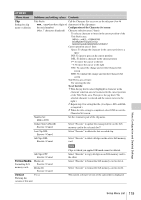
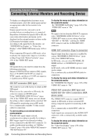
Connecting External Devices Connecting External Monitors and Recording Device To display recording/playback pictures on an external monitor, select the output signal and use an appropriate cable for the monitor to be connected. Output signal from the camcorder can be recorded when a recording device is connected. Regardless of whether the signal is HD or SD, the same status information and menus can be displayed on the external monitor as those on the LCD monitor/viewfinder screen. According to the signal fed to the monitor, set "SDI/HDMI Out Display" or "Video Out Display" of the VIDEO SET menu (page 108) to "On." When outputting SD signals in HD mode, select in advance the output mode (Squeeze, Letterbox, or Edge Crop) with "Down Converter" (page 109) of the VIDEO SET menu. Note SD signals down-converted for output have the following restrictions: Images of 50P/50i/25P are output as PAL signals, those of 59.94P/59.94i/29.97P are output as NTSC signals, and those of 23.98P are output as 2-3 pulled-down NTSC signals. SDI OUT connector (BNC type) The connector is set at the factory to output an HD SDI signal. When you set the camcorder to SD mode, the connector outputs an SD SDI signal. Using "SDI/HDMI/i.LINK I/O Select" (page 108) of the VIDEO SET menu, you can change the setting so that it outputs down-converted SD SDI signal for monitoring even in HD mode. Use a commercially available 75-ohm coaxial cable for connection. To start recording on an external device in synchronization With HD SDI signal output selected, synchronized recording is possible by feeding a REC trigger signal to an external recording device connected via the SDI OUT connector. To enable synchronized recording, set "SDI Rec Control" (page 109) of the VIDEO SET menu to "HD SDI Remote I/F." To display the menus and status information on the connected monitor Set "SDI/HDMI Out Display" (page 108) of the VIDEO SET menu to "On."Note Note No signal is fed out from the SDI OUT connector when "SDI/HDMI/i.LINK I/O Select" of the VIDEO SET menu is at any setting other than "HD SDI" or "SD SDI," enabling the HDMI OUT connector and the i.LINK (HDV/DV) connector. HDMI OUT connector (Type A connector) Signal output from this connector is enabled by setting "SDI/HDMI/i.LINK I/O Select" (page 108) of the VIDEO SET menu. In HD mode, you can select HD HDMI, SD HDMI interlace, or SD HDMI Progressive output. In SD mode, only an SD HDMI interlace signal can be output. Use a commercially available HDMI cable for connection. To display the menus and status information on the connected monitor Set "SDI/HDMI Out Display" (page 108) of the VIDEO SET menu to "On." VIDEO OUT connector (BNC type) and AUDIO OUT CH-1/CH-2 connectors (RCA phono jacks) The VIDEO OUT connector outputs HD-Y signals in HD mode or down-converted SD analog composite signals for monitoring in SD mode. Use a commercially available BNC cable for connection. Audio signals are connected via the AUDIO OUT connectors with a commercially available audio cables. To display the menus and status information on the connected monitor Set "Video Out Display" (page 109) of the VIDEO SET menu to "On." Connecting External Devices 124 Connecting External Monitors and Recording Device
-
 1
1 -
2
-
3
-
4
-
5
-
6
-
7
-
8
-
9
-
10
-
11
-
12
-
13
-
14
-
15
-
16
-
17
-
18
-
19
-
20
-
21
-
22
-
23
-
24
-
25
-
26
-
27
-
28
-
29
-
30
-
31
-
32
-
33
-
34
-
35
-
36
-
37
-
38
-
39
-
40
-
41
-
42
-
43
-
44
-
45
-
46
-
47
-
48
-
49
-
50
-
51
-
52
-
53
-
54
-
55
-
56
-
57
-
58
-
59
-
60
-
61
-
62
-
63
-
64
-
65
-
66
-
67
-
68
-
69
-
70
-
71
-
72
-
73
-
74
-
75
-
76
-
77
-
78
-
79
-
80
-
81
-
82
-
83
-
84
-
85
-
86
-
87
-
88
-
89
-
90
-
91
-
92
-
93
-
94
-
95
-
96
-
97
-
98
-
99
-
100
-
101
-
102
-
103
-
104
-
105
-
106
-
107
-
108
-
109
-
110
-
111
-
112
-
113
-
114
-
115
-
116
-
117
-
118
-
 119
119 -
 120
120 -
 121
121 -
 122
122 -
 123
123 -
 124
124 -
 125
125 -
 126
126 -
 127
127 -
 128
128 -
 129
129 -
130
-
131
-
132
-
133
-
134
-
135
-
136
-
137
-
138
-
139
-
140
-
141
-
142
-
143
-
144
-
145
-
146
-
147
-
148
-
149
-
150
 |
 |
