Yamaha MD4S Owner's Manual - Page 20
Time counter mode, MIDI indicators, Track level meters, Stereo level meter, CUE MIX indicator - transmission
 |
View all Yamaha MD4S manuals
Add to My Manuals
Save this manual to your list of manuals |
Page 20 highlights
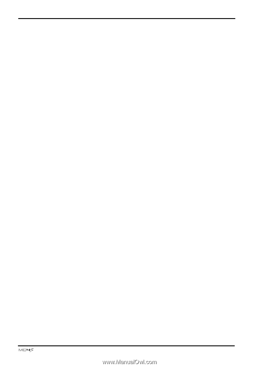
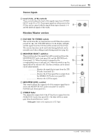
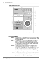
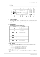
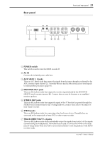
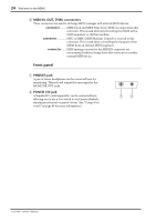
20 Welcome to the MD4S E Time counter mode This indicates the time counter mode that was selected by the DISPLAY button (disc transport M). However if a tempo map has been programmed and the time counter is showing measure/beat/clock, all of these indicators will be dark. ELAPSE TIME ...... The time counter will show the current elapsed time within the song. TOTAL TIME......... The time counter will show the time position within the entire disc. REMAIN TIME ...... The time counter will show the remaining time within the son F MIDI indicators The status of various MIDI functions is shown here. MTC SYNC MASTER .......... This will light when you enable MTC transmission. In this case, the MD4S will transmit MTC and will function as the master of a synchronized MIDI system. MTC SYNC SLAVE This will light when you enable MTC reception. In this case, the MD4S will receive MTC and will function as a slave in a synchronized MIDI system. MIDI CLK This will light when you enable MIDI Clock transmission. In this case, the MD4S will transmit MIDI Clock and will function as the master of a synchronized MIDI system. MMC This will light when you enable MMC (MIDI Machine Control) reception. In this case, the MD4S can be controlled from an external device such as a MIDI sequencer. G Track level meters These indicate the recording/playback level of each track. The range from -39 dB to CLIP is shown in nine steps. The CLIP indicator will light to indicate that digital clipping has occurred in the signal. If no disc is inserted, these meters will indicate the input levels of input channels 1-4. H Stereo level meter This meter indicates the output level of the STEREO OUT jacks. The range from -20 dB to +12 dB is shown in nine steps. I CUE MIX indicator This indicates the on/off status of the cue mix function. If you record while the cue mix function is on, this indicator will blink, indicating that the cue mix function has been temporarily turned off. J Track recording indicators These indicate the recording status of each track. When a indicator is blinking, the corresponding track is ready to record. When recording begins, the blinking indicator will light solidly. DIR/1-4 These indicate tracks that have been selected for direct recording (in which the signal from the input channel is recorded directly). BUS/L, R These indicate tracks that have been selected for recording the signal from the ST bus (L or R channel). -Owner's Manual
-
 1
1 -
2
-
3
-
4
-
5
-
6
-
7
-
8
-
9
-
10
-
11
-
12
-
13
-
14
-
 15
15 -
 16
16 -
 17
17 -
 18
18 -
 19
19 -
 20
20 -
 21
21 -
 22
22 -
 23
23 -
 24
24 -
 25
25 -
26
-
27
-
28
-
29
-
30
-
31
-
32
-
33
-
34
-
35
-
36
-
37
-
38
-
39
-
40
-
41
-
42
-
43
-
44
-
45
-
46
-
47
-
48
-
49
-
50
-
51
-
52
-
53
-
54
-
55
-
56
-
57
-
58
-
59
-
60
-
61
-
62
-
63
-
64
-
65
-
66
-
67
-
68
-
69
-
70
-
71
-
72
-
73
-
74
-
75
-
76
-
77
-
78
-
79
-
80
-
81
-
82
-
83
-
84
-
85
-
86
-
87
-
88
-
89
-
90
-
91
-
92
-
93
-
94
-
95
-
96
-
97
-
98
-
99
-
100
-
101
-
102
-
103
-
104
-
105
-
106
-
107
-
108
-
109
-
110
-
111
-
112
-
113
-
114
-
115
 |
 |