Cisco 1601 Hardware Installation Guide - Page 109
Signal, RJ-45 Pin Assignment, Table 23, RJ-45 Signal Assignment by Pin
 |
View all Cisco 1601 manuals
Add to My Manuals
Save this manual to your list of manuals |
Page 109 highlights
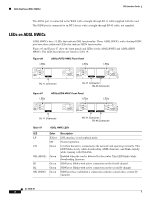
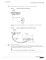
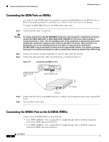
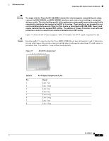
DSL Interface Cards Connecting a DSL Interface Card to the Network Warning To comply with the Telcordia GR-1089 NEBS standard for electromagnetic compatibility and safety, connect the HWIC-2SHDSL and HWIC-4SHDSL interface cards only to intra-building or unexposed wiring or cable. The intra-building port(s) of the equipment or subassembly must not be metallically connected to interfaces that connect to the OSP or its wiring. These interfaces are designed for use as intra-building interfaces only (Type 2 or Type 4 ports as described in GR-1089-CORE, Issue 4) and require isolation from the exposed OSP cabling. The addition of Primary Protectors is not sufficient protection in order to connect these interfaces metallically to OSP wiring. Figure 71 shows the RJ-45 pin assignment. Table 23 identifies the RJ-45 signal assignment by pin. Caution Inserting an RJ-11 connector into the Cisco HWIC-4SHDSL port may deform pins 1 and 8, which may prevent solid contact between the connector and the plug in subsequent connections. If solid contact is prevented, line -1 tip and line -3 ring will not work properly. Figure 71 RJ-45 Pin Assignment 12345678 170068 Table 23 Pin 1 2 3 4 5 6 7 8 RJ-45 Signal Assignment by Pin Signal Line 1 tip Line 1 ring Line 2 tip Line 0 tip Line 0 ring Line 2 ring Line 3 tip Line 3 ring OL-12846-01 13
-
 1
1 -
2
-
3
-
4
-
5
-
6
-
7
-
8
-
9
-
10
-
11
-
12
-
13
-
14
-
15
-
16
-
17
-
18
-
19
-
20
-
21
-
22
-
23
-
24
-
25
-
26
-
27
-
28
-
29
-
30
-
31
-
32
-
33
-
34
-
35
-
36
-
37
-
38
-
39
-
40
-
41
-
42
-
43
-
44
-
45
-
46
-
47
-
48
-
49
-
50
-
51
-
52
-
53
-
54
-
55
-
56
-
57
-
58
-
59
-
60
-
61
-
62
-
63
-
64
-
65
-
66
-
67
-
68
-
69
-
70
-
71
-
72
-
73
-
74
-
75
-
76
-
77
-
78
-
79
-
80
-
81
-
82
-
83
-
84
-
85
-
86
-
87
-
88
-
89
-
90
-
91
-
92
-
93
-
94
-
95
-
96
-
97
-
98
-
99
-
100
-
101
-
102
-
103
-
 104
104 -
 105
105 -
 106
106 -
 107
107 -
 108
108 -
 109
109 -
 110
110 -
 111
111 -
 112
112 -
 113
113 -
 114
114 -
115
-
116
-
117
-
118
-
119
-
120
-
121
-
122
-
123
-
124
-
125
-
126
-
127
-
128
-
129
-
130
-
131
-
132
-
133
-
134
-
135
-
136
-
137
-
138
-
139
-
140
-
141
-
142
-
143
-
144
-
145
-
146
-
147
-
148
-
149
-
150
-
151
-
152
-
153
-
154
-
155
-
156
-
157
-
158
-
159
-
160
-
161
-
162
-
163
-
164
-
165
-
166
-
167
-
168
-
169
-
170
-
171
-
172
-
173
-
174
-
175
-
176
-
177
-
178
-
179
-
180
-
181
-
182
-
183
-
184
-
185
-
186
-
187
-
188
-
189
-
190
-
191
-
192
-
193
-
194
-
195
-
196
-
197
-
198
-
199
-
200
-
201
-
202
-
203
-
204
-
205
-
206
-
207
-
208
-
209
-
210
-
211
-
212
-
213
-
214
-
215
-
216
 |
 |