Cisco 1601 Hardware Installation Guide - Page 124
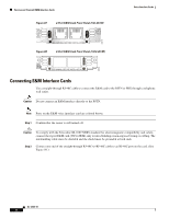
Connecting E&M Interface Cards, Port E&M Card Front Panel VIC-2E/M
 |
View all Cisco 1601 manuals
Add to My Manuals
Save this manual to your list of manuals |
Page 124 highlights
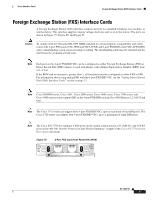
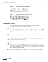
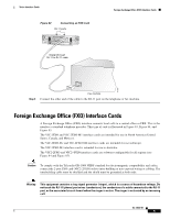
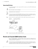
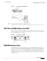
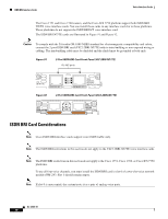
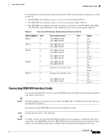
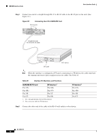
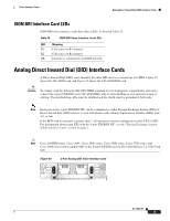
Receive and Transmit (E&M) Interface Cards Voice Interface Cards Figure 87 2-Port E&M Card Front Panel (VIC-2E/M) IN USE 41219 IN USE VIC E&M 1 SEE MANUAL BEFORE INSTALLATION 0 Figure 88 2-Port E&M Card Front Panel (VIC2-2E/M) IN USE 89039 IN USE VIC22E/M 1 SEE MANUAL BEFORE INSTALLATION 0 Connecting E&M Interface Cards Use a straight-through RJ-48C cable to connect the E&M card to the PSTN or PBX through a telephone wall outlet. Caution Do not connect an E&M interface directly to the PSTN. Note Ports on the E&M voice interface card are colored brown. Step 1 Confirm that the router is still turned off. Caution To comply with the Telcordia GR-1089 NEBS standard for electromagnetic compatibility and safety, connect the 2-port E&M card (VIC2-2E/M) only to intra-building or non-exposed wiring or cabling. The intrabuilding cable must be shielded and the shield must be grounded at both ends. Step 2 Connect one end of the straight-through RJ-48C-to-RJ-48C cable to an RJ-48C port on the card. (See Figure 89.) OL-12847-01 8
-
 1
1 -
2
-
3
-
4
-
5
-
6
-
7
-
8
-
9
-
10
-
11
-
12
-
13
-
14
-
15
-
16
-
17
-
18
-
19
-
20
-
21
-
22
-
23
-
24
-
25
-
26
-
27
-
28
-
29
-
30
-
31
-
32
-
33
-
34
-
35
-
36
-
37
-
38
-
39
-
40
-
41
-
42
-
43
-
44
-
45
-
46
-
47
-
48
-
49
-
50
-
51
-
52
-
53
-
54
-
55
-
56
-
57
-
58
-
59
-
60
-
61
-
62
-
63
-
64
-
65
-
66
-
67
-
68
-
69
-
70
-
71
-
72
-
73
-
74
-
75
-
76
-
77
-
78
-
79
-
80
-
81
-
82
-
83
-
84
-
85
-
86
-
87
-
88
-
89
-
90
-
91
-
92
-
93
-
94
-
95
-
96
-
97
-
98
-
99
-
100
-
101
-
102
-
103
-
104
-
105
-
106
-
107
-
108
-
109
-
110
-
111
-
112
-
113
-
114
-
115
-
116
-
117
-
118
-
 119
119 -
 120
120 -
 121
121 -
 122
122 -
 123
123 -
 124
124 -
 125
125 -
 126
126 -
 127
127 -
 128
128 -
 129
129 -
130
-
131
-
132
-
133
-
134
-
135
-
136
-
137
-
138
-
139
-
140
-
141
-
142
-
143
-
144
-
145
-
146
-
147
-
148
-
149
-
150
-
151
-
152
-
153
-
154
-
155
-
156
-
157
-
158
-
159
-
160
-
161
-
162
-
163
-
164
-
165
-
166
-
167
-
168
-
169
-
170
-
171
-
172
-
173
-
174
-
175
-
176
-
177
-
178
-
179
-
180
-
181
-
182
-
183
-
184
-
185
-
186
-
187
-
188
-
189
-
190
-
191
-
192
-
193
-
194
-
195
-
196
-
197
-
198
-
199
-
200
-
201
-
202
-
203
-
204
-
205
-
206
-
207
-
208
-
209
-
210
-
211
-
212
-
213
-
214
-
215
-
216
 |
 |