Cisco 1601 Hardware Installation Guide - Page 118
Cisco 1700 Series Routers, Cisco 2600 Series, Cisco ICS 7750, Pinout and Cabling Specifications
 |
View all Cisco 1601 manuals
Add to My Manuals
Save this manual to your list of manuals |
Page 118 highlights
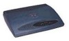
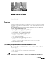
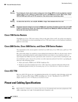
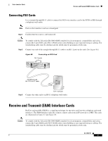
Pinout and Cabling Specifications Voice Interface Cards Warning To avoid electric shock, do not connect safety extra-low voltage (SELV) circuits to telephone-network voltage (TNV) circuits. LAN ports contain SELV circuits, and WAN ports contain TNV circuits. Some LAN and WAN ports both use RJ-45 connectors. Use caution when connecting cables. Warning To reduce the risk of fire, use only No. 26 AWG or larger telecommunication line cord. Warning Hazardous network voltages are present in WAN ports regardless of whether power to the unit is OFF or ON. To avoid electric shock, use caution when working near WAN ports. When detaching cables, detach the end away from the unit first. Cisco 1700 Series Routers Grounding on a Cisco 1700 series router is done on the router chassis itself, not on the voice interface cards. For information on chassis grounding on Cisco 1700 series routers, see the hardware installation guide for your router. Cisco 2600 Series, Cisco 3600 Series, and Cisco 3700 Series Routers The requirements in this section apply to only the Cisco 2600 series, Cisco 3600 series, and Cisco 3700 series routers. The cards in this chapter are suitable for exposed plant lead connection. However, the host router chassis must have a permanent protective earth connection before you connect a voice interface card to an exposed plant lead. Make sure that a permanent earth connection is in place before installing the card. If you find that a router chassis does not have an earth connection and you do not have a grounding kit, take one of the following actions: • Order and install a NEBS Level 3/ETSI Compliance Kit. • Install an equivalent permanent protective earth connection, using the method described in the installation guide Installing the Grounding Lug on Cisco 2600 and Cisco 3600 Series Routers. Cisco ICS 7750 The Cisco ICS 7750 chassis has a grounding lug that needs to be properly connected using a green and yellow 14 American Wire Gauge (AWG) grounding wire. See the "Installing the Cisco ICS 7750" chapter in the Cisco ICS 7750 Hardware Installation Guide. Pinout and Cabling Specifications Note Refer to the Cisco Modular Access Router Specifications for network-end connectors and pinouts of the cables connecting voice cards. Look under the type of interface card. OL-12847-01 2
-
 1
1 -
2
-
3
-
4
-
5
-
6
-
7
-
8
-
9
-
10
-
11
-
12
-
13
-
14
-
15
-
16
-
17
-
18
-
19
-
20
-
21
-
22
-
23
-
24
-
25
-
26
-
27
-
28
-
29
-
30
-
31
-
32
-
33
-
34
-
35
-
36
-
37
-
38
-
39
-
40
-
41
-
42
-
43
-
44
-
45
-
46
-
47
-
48
-
49
-
50
-
51
-
52
-
53
-
54
-
55
-
56
-
57
-
58
-
59
-
60
-
61
-
62
-
63
-
64
-
65
-
66
-
67
-
68
-
69
-
70
-
71
-
72
-
73
-
74
-
75
-
76
-
77
-
78
-
79
-
80
-
81
-
82
-
83
-
84
-
85
-
86
-
87
-
88
-
89
-
90
-
91
-
92
-
93
-
94
-
95
-
96
-
97
-
98
-
99
-
100
-
101
-
102
-
103
-
104
-
105
-
106
-
107
-
108
-
109
-
110
-
111
-
112
-
 113
113 -
 114
114 -
 115
115 -
 116
116 -
 117
117 -
 118
118 -
 119
119 -
 120
120 -
 121
121 -
 122
122 -
 123
123 -
124
-
125
-
126
-
127
-
128
-
129
-
130
-
131
-
132
-
133
-
134
-
135
-
136
-
137
-
138
-
139
-
140
-
141
-
142
-
143
-
144
-
145
-
146
-
147
-
148
-
149
-
150
-
151
-
152
-
153
-
154
-
155
-
156
-
157
-
158
-
159
-
160
-
161
-
162
-
163
-
164
-
165
-
166
-
167
-
168
-
169
-
170
-
171
-
172
-
173
-
174
-
175
-
176
-
177
-
178
-
179
-
180
-
181
-
182
-
183
-
184
-
185
-
186
-
187
-
188
-
189
-
190
-
191
-
192
-
193
-
194
-
195
-
196
-
197
-
198
-
199
-
200
-
201
-
202
-
203
-
204
-
205
-
206
-
207
-
208
-
209
-
210
-
211
-
212
-
213
-
214
-
215
-
216
 |
 |