Cisco 1601 Hardware Installation Guide - Page 49
Removing Blank, Faceplates
 |
View all Cisco 1601 manuals
Add to My Manuals
Save this manual to your list of manuals |
Page 49 highlights
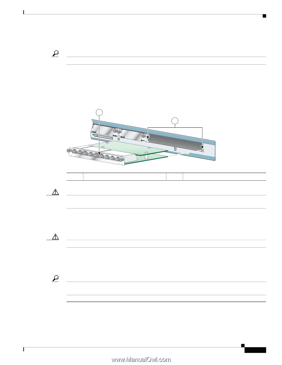
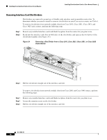
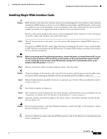
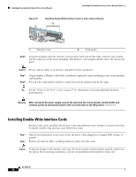
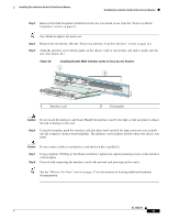
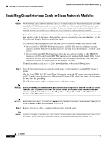
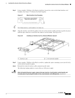
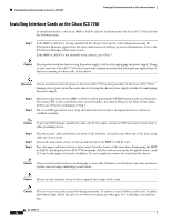
Installing Cisco Interface Cards in Cisco Access Routers Installing Cisco Interface Cards in Cisco Access Routers Step 3 Remove the blank faceplates installed over the slot you intend to use. (See the "Removing Blank Faceplates" section on page 8.) Tip Save blank faceplates for future use. Step 4 Remove the slot divider. (See the "Removing Interface Card Slot Dividers" section on page 14.) Step 5 Align the interface card with the guides in the chassis walls or slot divider, and slide it gently into the slot. (See Figure 26.) Figure 26 Installing Double-Wide Interface Cards in Cisco Access Routers 1 2 121079 1 Interface card 2 Card guides Caution Do not touch the interface card board. Handle the interface card by the edges of the faceplate to reduce the risk of damage to the card. Step 6 Using the faceplate, push the interface card into place until you feel the edge connector seat securely into the connector on the router backplane. The interface card faceplate should contact the chassis rear panel. Caution Do not connect cables to an interface card until you have installed it. Step 7 Step 8 Using a number 1 Phillips or flat-blade screwdriver, tighten the captive mounting screws on the interface card faceplate. Proceed with connecting the interface card to the network and powering up the router. Tip See the "Where to Go Next" section on page 27 for information on locating additional hardware documentation. OL-12842-01 17
-
 1
1 -
2
-
3
-
4
-
5
-
6
-
7
-
8
-
9
-
10
-
11
-
12
-
13
-
14
-
15
-
16
-
17
-
18
-
19
-
20
-
21
-
22
-
23
-
24
-
25
-
26
-
27
-
28
-
29
-
30
-
31
-
32
-
33
-
34
-
35
-
36
-
37
-
38
-
39
-
40
-
41
-
42
-
43
-
 44
44 -
 45
45 -
 46
46 -
 47
47 -
 48
48 -
 49
49 -
 50
50 -
 51
51 -
 52
52 -
 53
53 -
 54
54 -
55
-
56
-
57
-
58
-
59
-
60
-
61
-
62
-
63
-
64
-
65
-
66
-
67
-
68
-
69
-
70
-
71
-
72
-
73
-
74
-
75
-
76
-
77
-
78
-
79
-
80
-
81
-
82
-
83
-
84
-
85
-
86
-
87
-
88
-
89
-
90
-
91
-
92
-
93
-
94
-
95
-
96
-
97
-
98
-
99
-
100
-
101
-
102
-
103
-
104
-
105
-
106
-
107
-
108
-
109
-
110
-
111
-
112
-
113
-
114
-
115
-
116
-
117
-
118
-
119
-
120
-
121
-
122
-
123
-
124
-
125
-
126
-
127
-
128
-
129
-
130
-
131
-
132
-
133
-
134
-
135
-
136
-
137
-
138
-
139
-
140
-
141
-
142
-
143
-
144
-
145
-
146
-
147
-
148
-
149
-
150
-
151
-
152
-
153
-
154
-
155
-
156
-
157
-
158
-
159
-
160
-
161
-
162
-
163
-
164
-
165
-
166
-
167
-
168
-
169
-
170
-
171
-
172
-
173
-
174
-
175
-
176
-
177
-
178
-
179
-
180
-
181
-
182
-
183
-
184
-
185
-
186
-
187
-
188
-
189
-
190
-
191
-
192
-
193
-
194
-
195
-
196
-
197
-
198
-
199
-
200
-
201
-
202
-
203
-
204
-
205
-
206
-
207
-
208
-
209
-
210
-
211
-
212
-
213
-
214
-
215
-
216
 |
 |