Cisco 1601 Hardware Installation Guide - Page 120
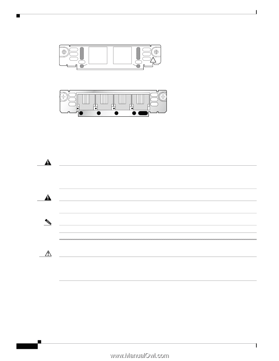
Connecting FXS Cards, Port FXS Card Front Panel VIC2-2FXS
 |
View all Cisco 1601 manuals
Add to My Manuals
Save this manual to your list of manuals |
Page 120 highlights
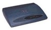
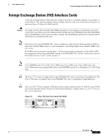
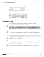
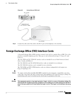
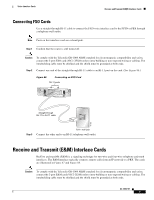
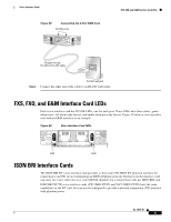
Foreign Exchange Station (FXS) Interface Cards Figure 80 2-Port FXS Card Front Panel (VIC2-2FXS) IN USE 89041 IN USE VIC22FXS ! 1 SEE MANUAL BEFORE INSTALLATION 0 Figure 81 4-Port FXS/DID Card Front Panel (VIC-4FXS/DID) Voice Interface Cards 65683 VIC 4FXS/DID 3 2 1 0 IN USE Connecting FXS Cards Use a standard straight-through RJ-11 modular telephone cable to connect a VIC-2FXS, VIC-4FXS/DID, or VIC2-2FXS to a telephone or fax machine. Warning This equipment contains a ring signal generator (ringer), which is a source of hazardous voltage. Do not touch the RJ-11 (phone) port wires (conductors), the conductors of a cable connected to the RJ-11 port, or the associated circuit-board when the ringer is active. The ringer is activated by an incoming call. Warning For connections outside the building where the equipment is installed, the following ports must be connected through an approved network termination unit with integral circuit protection: FXS. Note Ports on this interface card are colored gray. Step 1 Confirm that the router is still turned off. Caution To comply with the Telcordia GR-1089 NEBS standard for electromagnetic compatibility and safety, connect the 2-port FXS cards (VIC-2FXS and VIC2-2FXS) and 4-port FXS/DID cards (VIC-4FXS/DID) only to intra-building or non-exposed wiring or cabling. The intrabuilding cable must be shielded and the shield must be grounded at both ends. Step 2 Connect one end of the straight-through RJ-11 cable to an RJ-11 port on the card. (See Figure 82.) OL-12847-01 4
-
 1
1 -
2
-
3
-
4
-
5
-
6
-
7
-
8
-
9
-
10
-
11
-
12
-
13
-
14
-
15
-
16
-
17
-
18
-
19
-
20
-
21
-
22
-
23
-
24
-
25
-
26
-
27
-
28
-
29
-
30
-
31
-
32
-
33
-
34
-
35
-
36
-
37
-
38
-
39
-
40
-
41
-
42
-
43
-
44
-
45
-
46
-
47
-
48
-
49
-
50
-
51
-
52
-
53
-
54
-
55
-
56
-
57
-
58
-
59
-
60
-
61
-
62
-
63
-
64
-
65
-
66
-
67
-
68
-
69
-
70
-
71
-
72
-
73
-
74
-
75
-
76
-
77
-
78
-
79
-
80
-
81
-
82
-
83
-
84
-
85
-
86
-
87
-
88
-
89
-
90
-
91
-
92
-
93
-
94
-
95
-
96
-
97
-
98
-
99
-
100
-
101
-
102
-
103
-
104
-
105
-
106
-
107
-
108
-
109
-
110
-
111
-
112
-
113
-
114
-
 115
115 -
 116
116 -
 117
117 -
 118
118 -
 119
119 -
 120
120 -
 121
121 -
 122
122 -
 123
123 -
 124
124 -
 125
125 -
126
-
127
-
128
-
129
-
130
-
131
-
132
-
133
-
134
-
135
-
136
-
137
-
138
-
139
-
140
-
141
-
142
-
143
-
144
-
145
-
146
-
147
-
148
-
149
-
150
-
151
-
152
-
153
-
154
-
155
-
156
-
157
-
158
-
159
-
160
-
161
-
162
-
163
-
164
-
165
-
166
-
167
-
168
-
169
-
170
-
171
-
172
-
173
-
174
-
175
-
176
-
177
-
178
-
179
-
180
-
181
-
182
-
183
-
184
-
185
-
186
-
187
-
188
-
189
-
190
-
191
-
192
-
193
-
194
-
195
-
196
-
197
-
198
-
199
-
200
-
201
-
202
-
203
-
204
-
205
-
206
-
207
-
208
-
209
-
210
-
211
-
212
-
213
-
214
-
215
-
216
 |
 |