Cisco 1601 Hardware Installation Guide - Page 122
Setting Jumpers on the 2-Port FXO Card, Port FXO Card Front Panel VIC-2FXO
 |
View all Cisco 1601 manuals
Add to My Manuals
Save this manual to your list of manuals |
Page 122 highlights
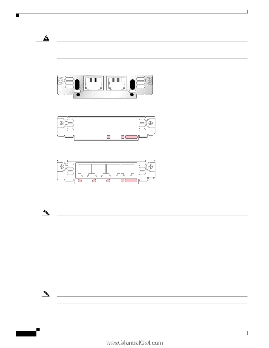
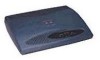
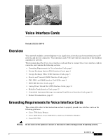
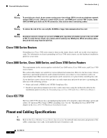
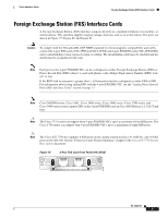
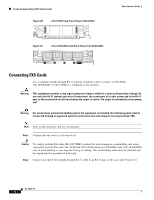
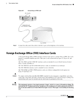
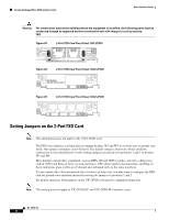
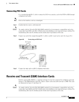
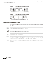
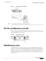
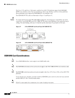
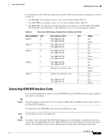
Foreign Exchange Office (FXO) Interface Cards Voice Interface Cards Warning For connections outside the building where the equipment is installed, the following ports must be connected through an approved network termination unit with integral circuit protection. FXO Figure 83 2-Port FXO Card Front Panel (VIC-2FXO) IN USE 41217 IN USE VIC FXO 1 SEE MANUAL BEFORE INSTALLATION 0 Figure 84 2-Port FXO Card Front Panel (VIC2-2FXO) VIC22FXO SEE MANUAL BEFORE INSTALLATION 1 0 IN USE 89038 Figure 85 4-Port FXO Card Front Panel (VIC2-4FXO) 89040 VIC24FXO 3 2 1 0 IN USE Setting Jumpers on the 2-Port FXO Card Note This information does not apply to the VIC2-2FXO card. The FXO voice interface card includes two jumper headers, W3 and W4, to set loop-start or ground-start mode. One jumper configures each FXO port. The default setting is loop-start, which should be satisfactory in most installations. In this setting, jumpers are placed over positions 2 and 3 of headers W3 and W4. Most modern central office equipment, such as DMS-100 and 5ESS switches, provides calling party control (CPC) and Ring on Seize on loop-start lines. CPC allows quicker disconnection, and Ring on Seize minimizes glare (collision of inbound and outbound calls on the same interface). If your central office does not provide these features on loop-start, you may want to configure the FXO card for ground-start operation instead by moving the jumpers to positions 1 and 2. For proper operation, both jumpers on the VIC-2FXO card must be configured identically. Note This setting does not apply to VIC-2FXO-EU and VIC-2FXO-M2 interface cards. OL-12847-01 6
-
 1
1 -
2
-
3
-
4
-
5
-
6
-
7
-
8
-
9
-
10
-
11
-
12
-
13
-
14
-
15
-
16
-
17
-
18
-
19
-
20
-
21
-
22
-
23
-
24
-
25
-
26
-
27
-
28
-
29
-
30
-
31
-
32
-
33
-
34
-
35
-
36
-
37
-
38
-
39
-
40
-
41
-
42
-
43
-
44
-
45
-
46
-
47
-
48
-
49
-
50
-
51
-
52
-
53
-
54
-
55
-
56
-
57
-
58
-
59
-
60
-
61
-
62
-
63
-
64
-
65
-
66
-
67
-
68
-
69
-
70
-
71
-
72
-
73
-
74
-
75
-
76
-
77
-
78
-
79
-
80
-
81
-
82
-
83
-
84
-
85
-
86
-
87
-
88
-
89
-
90
-
91
-
92
-
93
-
94
-
95
-
96
-
97
-
98
-
99
-
100
-
101
-
102
-
103
-
104
-
105
-
106
-
107
-
108
-
109
-
110
-
111
-
112
-
113
-
114
-
115
-
116
-
 117
117 -
 118
118 -
 119
119 -
 120
120 -
 121
121 -
 122
122 -
 123
123 -
 124
124 -
 125
125 -
 126
126 -
 127
127 -
128
-
129
-
130
-
131
-
132
-
133
-
134
-
135
-
136
-
137
-
138
-
139
-
140
-
141
-
142
-
143
-
144
-
145
-
146
-
147
-
148
-
149
-
150
-
151
-
152
-
153
-
154
-
155
-
156
-
157
-
158
-
159
-
160
-
161
-
162
-
163
-
164
-
165
-
166
-
167
-
168
-
169
-
170
-
171
-
172
-
173
-
174
-
175
-
176
-
177
-
178
-
179
-
180
-
181
-
182
-
183
-
184
-
185
-
186
-
187
-
188
-
189
-
190
-
191
-
192
-
193
-
194
-
195
-
196
-
197
-
198
-
199
-
200
-
201
-
202
-
203
-
204
-
205
-
206
-
207
-
208
-
209
-
210
-
211
-
212
-
213
-
214
-
215
-
216
 |
 |